UPD750104 データシートの表示(PDF) - NEC => Renesas Technology
部品番号
コンポーネント説明
メーカー
UPD750104 Datasheet PDF : 80 Pages
| |||
µPD750104, 750106, 750108, 750104(A), 750106(A), 750108(A)
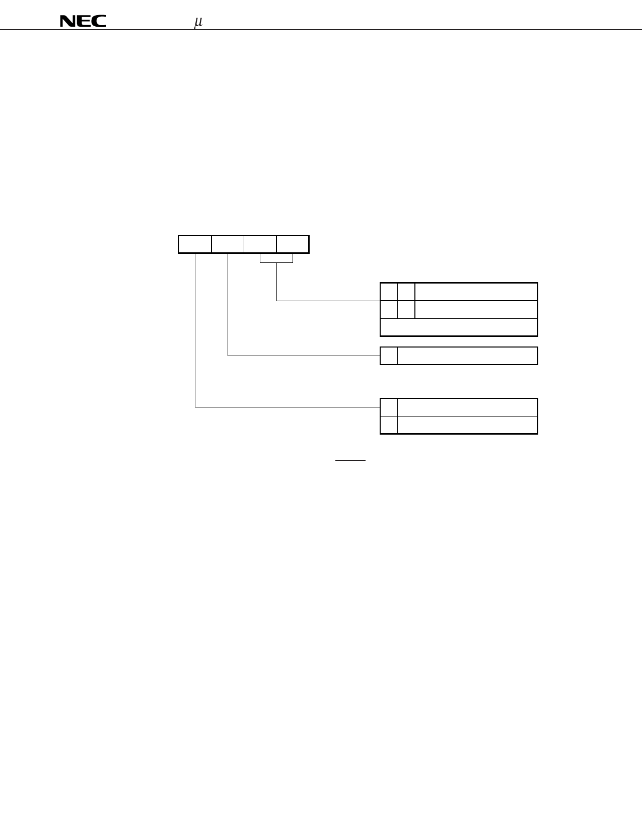
4.2 Setting of the Stack Bank Selection Register (SBS)
The Mk Ι mode and Mk ΙΙ mode are switched by stack bank selection register. Figure 4-1 shows the register
configuration.
The stack bank selection register is set with a 4-bit memory operation instruction. To use the CPU in Mk Ι mode,
initialize the register to 100×BNote at the beginning of the program. To use the CPU in Mk ΙΙ mode, initialize it to
000×BNote.
Note Specify the desired value in ×.
Figure 4-1. Stack Bank Selection Register Format
Address
F84H
3
2
1
0
SBS3 SBS2 SBS1 SBS0
Symbol
SBS
Stack area designation
0 0 Memory bank 0
0 1 Memory bank 1
Other settings are inhibited.
0 Bit 2 must be set to 0.
Mode switching designation
0 Mk ΙΙ mode
1 Mk Ι mode
Caution The CPU operates in Mk Ι mode after the RESET signal is issued, because bit 3 of SBS is set to
1. Set bit 3 of SBS to 0 (Mk ΙΙ mode) to use the CPU in Mk ΙΙ mode.
15
Share Link: 