F81865F データシートの表示(PDF) - Feature Integration Technology Inc.
部品番号
コンポーネント説明
メーカー
F81865F Datasheet PDF : 128 Pages
| |||
F81865
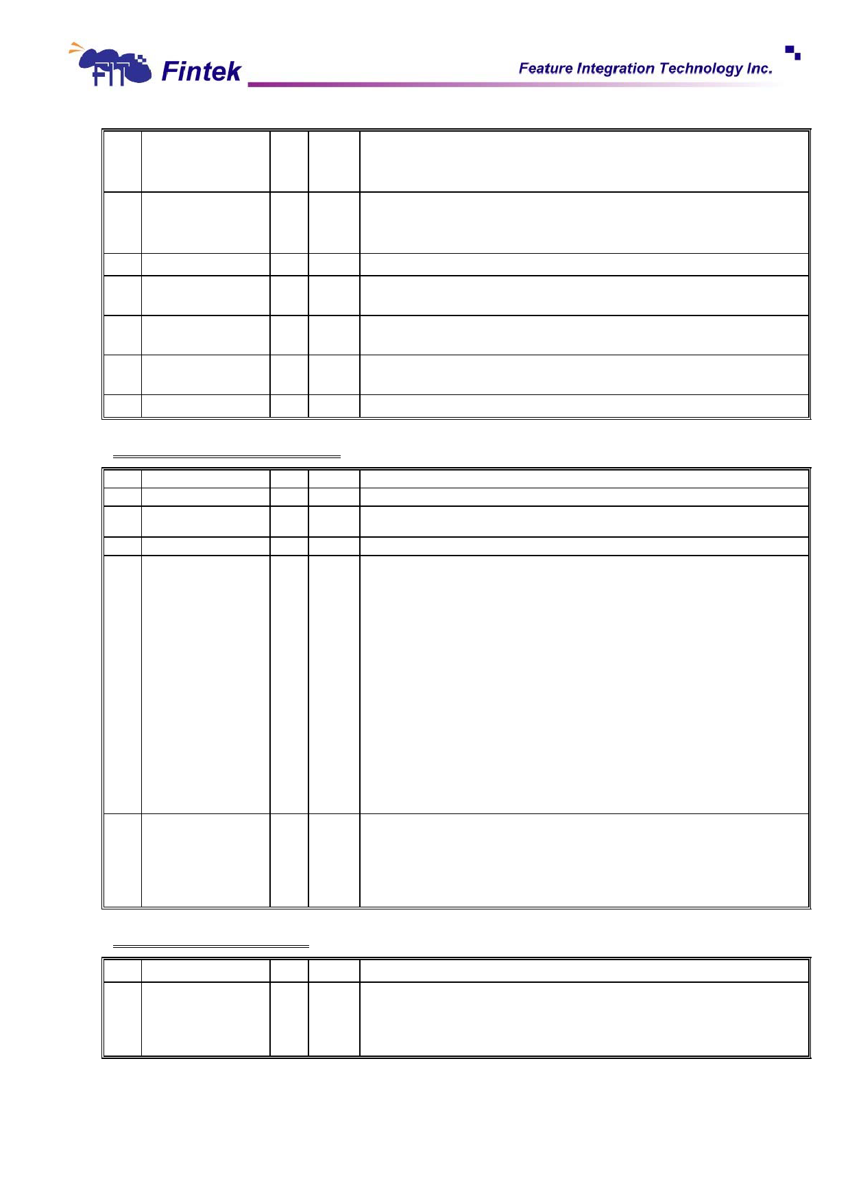
Data I/O (direction):
6
DIO
R
0 0: the controller is expecting a byte to be written to the Data Register.
1: the controller is expecting a byte to be read from the Data Register.
Non DMA Mode:
5
NON_DMA
R
0 0: the controller is in DAM mode.
1: the controller is interrupt or software polling mode.
4
FDC_BUSY
R
0 This bit indicate that a read or write command is in process.
3
DRV3_BUSY
R
0
FDD number 3 is in seek or calibration condition. FDD number 3 is not support
in this design.
FDD number 2 is in seek or calibration condition. FDD number 2 is not support
2
DRV2_BUSY
R
0 in this design.
1
DRV1_BUSY
R
0 FDD number 1 is in seek or calibration condition. FDD number 1 is not support
in this design.
0
DRV0_BUSY
R
0 FDD number 0 is in seek or calibration condition.
Data Rate Select Register ⎯ Base + 4
Bit
Name
R/W Default
Description
7
SOFTRST
W
0 A 1 written to this bit will software reset the controller. Auto clear after reset.
6
PWRDOWN
W
0
A 1 to this bit will put the controller into low power mode which will turn off the
oscillator and data separator circuits.
5
Reserved
-
- Return 0 when read.
4-2
PRECOMP
Select the value of write precompensation:
250K-1Mbps
2Mbps
000: default delays
default delays
001: 41.67ns
20.8ns
010: 83.34ns
41.17ns
011: 125.00ns
62.5ns
100: 166.67ns
83.3ns
101: 208.33ns
104.2ns
W 000 110: 250.00ns
125.00ns
111: 0.00ns (disabled)
0.00ns (disabled)
1-0
DRATE
The default value of corresponding data rate:
250Kbps: 125ns
300Kbps: 125ns
500Kbps: 125ns
1Mbps: 41.67ns
2Mbps: 20.8ns
Data rate select:
MFM
W
10
00: 500Kbps
01: 300Kbps
10: 250Kbps
11: 1Mbps
FM
250Kbps
150Kbps
125Kbps
illegal
Data (FIFO) Register ⎯ Base + 5
Bit
Name
R/W Default
Description
The FIFO is used to transfer all commands, data and status between controller
7-0
DATA
R/W
00h
and the system. The Data Register consists of four status registers in a stack
with only one register presented to the data bus at a time. The FIFO is default
disabled and could be enabled via the CONFIGURE command.
23
May, 2010
V0.28P
Share Link: 