AIT1042RS38P8 データシートの表示(PDF) - ANADIGICS
部品番号
コンポーネント説明
メーカー
AIT1042RS38P8 Datasheet PDF : 19 Pages
| |||
AIT1042
Upconverter Main and Reference Divider Registers
The upconverter main and reference divider registers are used to set the A, B and R counters in the upconverter
synthesizer. The output frequency for the synthesizer is computed using the following equation:
where:
fosc
=
[(16)(B) +
R
A]
fxtal
fOSC is the upconverter local oscillator (LO1) frequency
B is the divide ratio of the B counter (2 to 2047 inclusive)
A is the divide ratio of the A counter (0 < A < P-1, A < B)
fXTAL is the frequency of the reference crystal oscillator
R is the divide ratio of the R counter (2 to 1023 inclusive)
The preset modulus of the prescalar is 16 and is not programmable.
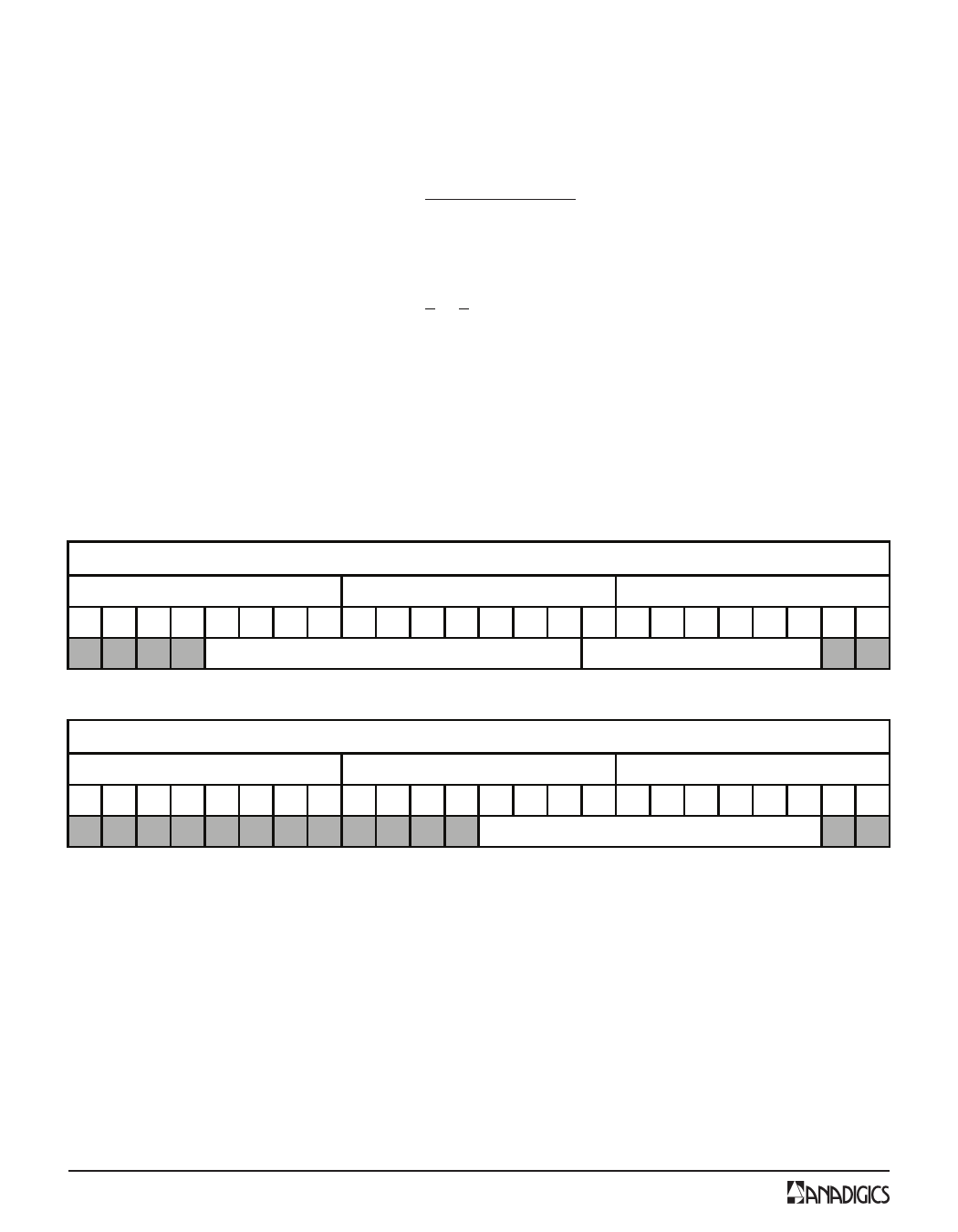
In the main divider register, the A counter is set via Bits 2-8 and the B counter is set with Bits 9-19. In the
reference divider register, the R counter is set with Bits 2-11. The remaining bits must use the fixed values
indicated in Tables 13 and 14.
MSB
Table 13: Upconverter Main Divider Register
PLL1_Main (Upconverter Main Divider Register)
First data byte
Second data byte
Third data byte
23 22 21 20 19 18 17 16 15 14 13 12 11 10 9 8 7 6 5 4 3 2
0000
B counter
A counter
LSB
10
11
MSB
Table 14: Upconverter Reference Divider Register
PLL1_Ref (Upconverter Reference Divider Register)
First data byte
Second data byte
Third data byte
23 22 21 20 19 18 17 16 15 14 13 12 11 10 9 8 7 6 5 4 3 2
000 100 100000
R counter
LSB
10
10
14
PRELIMINARY DATA SHEET - Rev 1.0
02/2009
Share Link: 