ATA6612P データシートの表示(PDF) - Atmel Corporation
部品番号
コンポーネント説明
メーカー
ATA6612P Datasheet PDF : 364 Pages
| |||
ATA6612/ATA6613
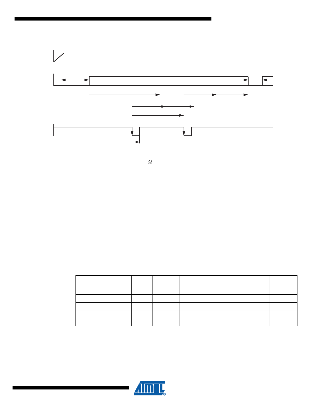
Figure 3-9. Timing Sequence with RWD_OSC = 51 kΩ
VCC
NRES
Undervoltage Reset
treset = 4 ms
NTRIG
td = 155 ms
t1
t1 = 20.6 ms t2 = 21 ms
twd
Watchdog Reset
tnres = 4 ms
t2
3.3.24.2
ttrig > 200 ns
Worst Case Calculation with RWO_OSC = 51 kΩ
The internal oscillator has a tolerance of 20%. This means that t1 and t2 can also vary by 20%.
The worst case calculation for the watchdog period twd is calculated as follows.
The ideal watchdog time twd is between the maximum t1 and the minimum t1 plus the minimum
t2.
t1,min = 0.8 × t1 = 16.5 ms, t1,max = 1.2 × t1 = 24.8 ms
t2,min = 0.8 × t2 = 17.3 ms, t2,max = 1.2 × t2 = 26 ms
twdmax = t1min + t2min = 16.5 ms + 17.3 ms = 33.8 ms
twdmin = t1max = 24.8 ms
twd = 29.3 ms ±4.5 ms (±15%)
A microcontroller with an oscillator tolerance of ±15% is sufficient to supply the trigger inputs
correctly.
Table 3-2.
RWD_OSC
kΩ
34
51
91
120
Typical Watchdog Timings
Oscillator
Period
tosc/µs
13.3
Lead
Time
td/ms
105
Closed
Window
t1/ms
14.0
19.61
154.8
20.64
33.54 264.80 35.32
42.84 338.22 45.11
Open Window
t2/ms
14.7
21.67
37.06
47.34
Trigger Period from
Microcontroller Reset Time
twd/ms
tnres/ms
19.9
4
29.32
4
50.14
4
64.05
4
19
9111G–AUTO–05/10
Share Link: 