NJU3151M データシートの表示(PDF) - Japan Radio Corporation
部品番号
コンポーネント説明
メーカー
NJU3151M Datasheet PDF : 11 Pages
| |||
NJU3151
s TERMINAL DESCRIPTION IN OTP PROGRAMMING MODE
No.
SYMBOL INPUT/OUTPUT
FUNCTION
9
1 - 4,
10 - 13,
14,
15
7
6
5
16
8
RESET
D0 - D7
CNT1
CNT2
REQ
CLK
PROM
VDD
VSS
INPUT
RESET terminal.
When the low-level input-signal, the system is initialized.
INPUT/OUTPUT Data bus
INPUT
INPUT
OUTPUT
INPUT
INPUT
-
-
OTP control input terminal
Request output terminal
Clock input terminal
OTP programming enable terminal
Power Source (5V)
Power Source (0V)
Note 1) Use at VDD=5V in OTP programming mode.
2) Non connect anything to the other terminals.
s Difference between NJU3151 (OTP version) and NJU3101 (MASK version)
q Operating mode
NJU3151 has two operating modes. One is ”Normal operating mode” and the other is “OTP programming
mode”.
• Normal operating mode
The ”TEST” terminal is set to low level. (The terminal is recommended to connect to GND.)
Operating voltage range; 2.7V ~ 5.5V.
• OTP Programming mode
User program is read out from or written into the OTP by the universal programmer “SUPERPRO/L” and
converting adapter made by XELTEK co,.(USA).
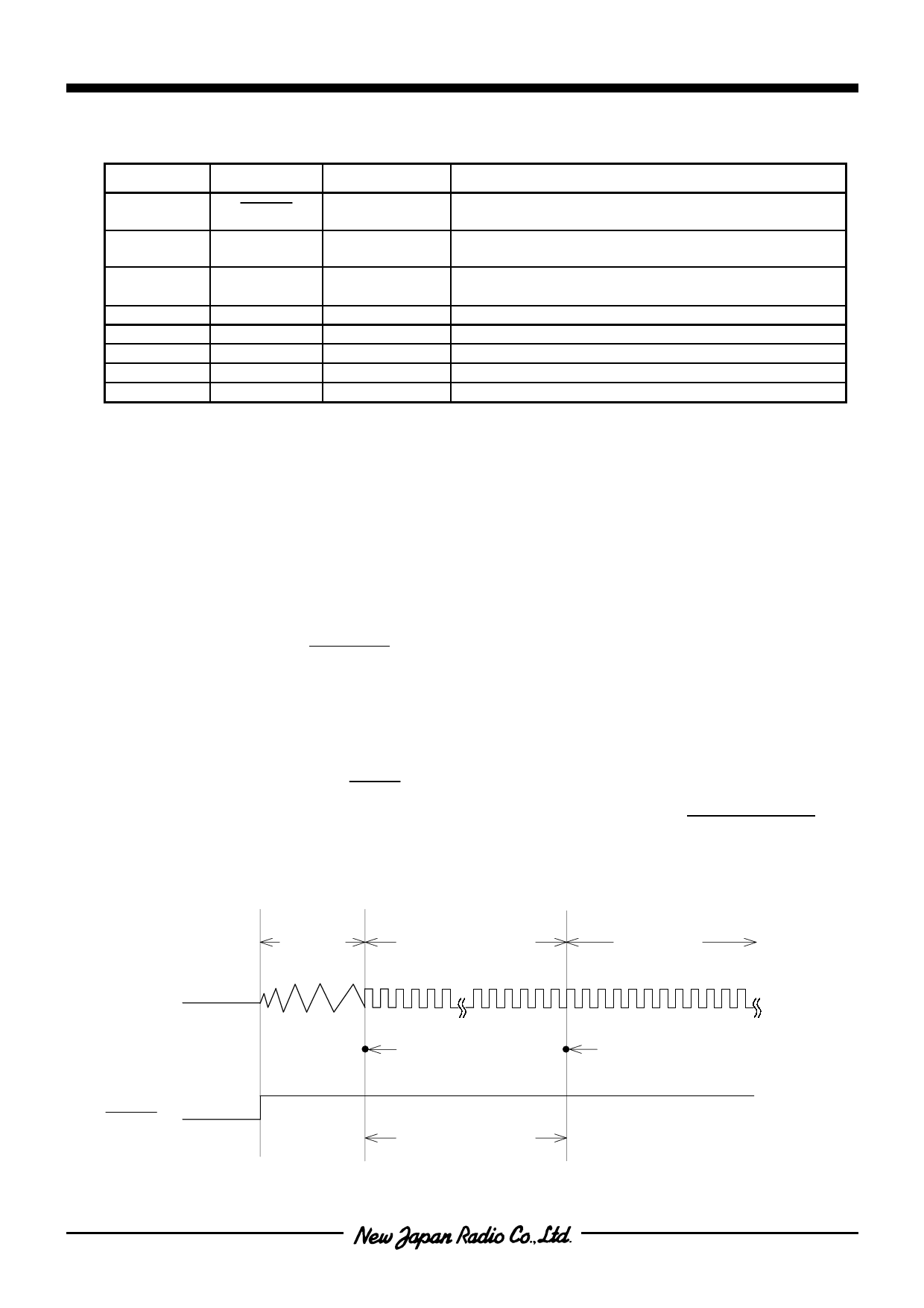
q Option information set in the initialization
When the initialization is performed(RESET terminal is “L”), the operation information stored in option area is
set as shown in the following timing chart . The option information is set in the term of 1 / fOSC x 256clock after
RESET releasing and oscillation stability time. After information set, the program counter is set to 0000H and
the NJU3151 operates in normal.
[ TIMING CHART ]
Oscillator
Clock
Oscillation
Stability
Time
Option information setting
1/fOSCx256clock
Normal
Operation
Oscillation
Start
PC=0000H
RESET
fOSC=4MHz
about 64µsec
-3-
Share Link: 