SM5L1 データシートの表示(PDF) - Sharp Electronics
部品番号
コンポーネント説明
メーカー
SM5L1 Datasheet PDF : 27 Pages
| |||
SM5L1/SM5L2/SM5L3
4-Bit Single Chip Microcomputers
When the IME flag is set, the interrupt circuit acti-
vates according to the interrupt request and a subrou-
tine jump is performed to the specified address. The
jump destinations according to interrupt origin are
shown in Table 5. When the IME flag is cleared, an
interrupt is not accepted even if an interrupt request is
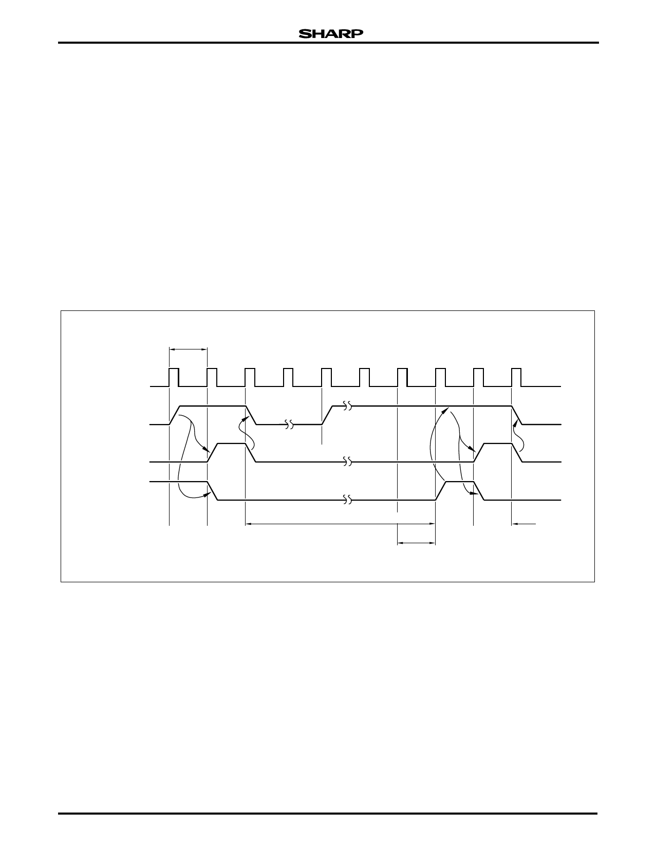
generated. The interrupt timing is shown in Figure 25
and Figure 26. The timing chart in Figure 25 shows the
interrupt enable state when an interrupt request has
been generated. In this case, the interrupt processing
signal INT goes HIGH, one instruction cycle after the
interrupt request flag is set. When INT goes HIGH, the
contents of the program counter are pushed into the
stack register and execution jumps to the specified
address. At this time, the INT signal and the IME flag
are cleared to establish the interrupt disable mode. The
IME flag is set again when the RTNI instruction is exe-
cuted to establish the interrupt enable mode.
The timing chart shown in Figure 26 shows the state
when interrupts are enabled while multiple interrupts
are generated. In this case, a subroutine jump is per-
formed according to the interrupt having the highest pri-
ority. When returning from the subroutine by executing
the RTNI instruction, the instruction (two words are
executed for a two-word instruction) at the location of
return is executed and the interrupt for the next highest
priority is accepted.
If an interrupt request is generated during execution
of a two cycle instruction, the instruction is executed
after which interrupt processing is performed. If con-
secutive LAX instructions are skipped or if the SKIP
conditions are satisfied, the skip operation is termi-
nated after which interrupt processing is performed.
NOTE: Figures 25 and 26 show non-masked interrupt request flags.
INSTRUCTION
CYCLE
SYSTEM CLOCK
INTERRUPT
REQUEST FLAG
INT SIGNAL
INTERRUPT
ENABLE FLAG
INTERRUPT PROCESSING ROUTINE
RTNI
INSTRUCTION
Figure 25. Interrupt Timing Chart
INTERRUPT
PROCESSING
ROUTINE
5L1-25
20
Microcomputer Data Sheet
Share Link: 