HT81009(2005) データシートの表示(PDF) - Holtek Semiconductor
部品番号
コンポーネント説明
メーカー
HT81009 Datasheet PDF : 19 Pages
| |||
HT81XXX
· 6Hz/6HzB flash
When voices are playing, the FLAG1 pin outputs a
6Hz signal to drive a LED. The signal is active low,
25% duty. Once the voice output is terminated, the
FLAG1 pin becomes a floating output. When the
FLAG1 and the FLAG2 pins are optioned as 6HzB
and 6Hz outputs, they will alternately output at a
6Hz rate.
AUD
FLA G
: F lo a tin g
· Busy output
When a voice group is playing, the outputs of both
FLAG1 and FLAG2 are turned low, indicating that the
chip is busy.
AUD
Volume Control
The function of the volume control can be set by mask
option. A code is written in the function table for the pur-
pose of controlling the volume of each section output af-
ter the volume control function is chosen. There are two
volume options, namely; full range and half range.
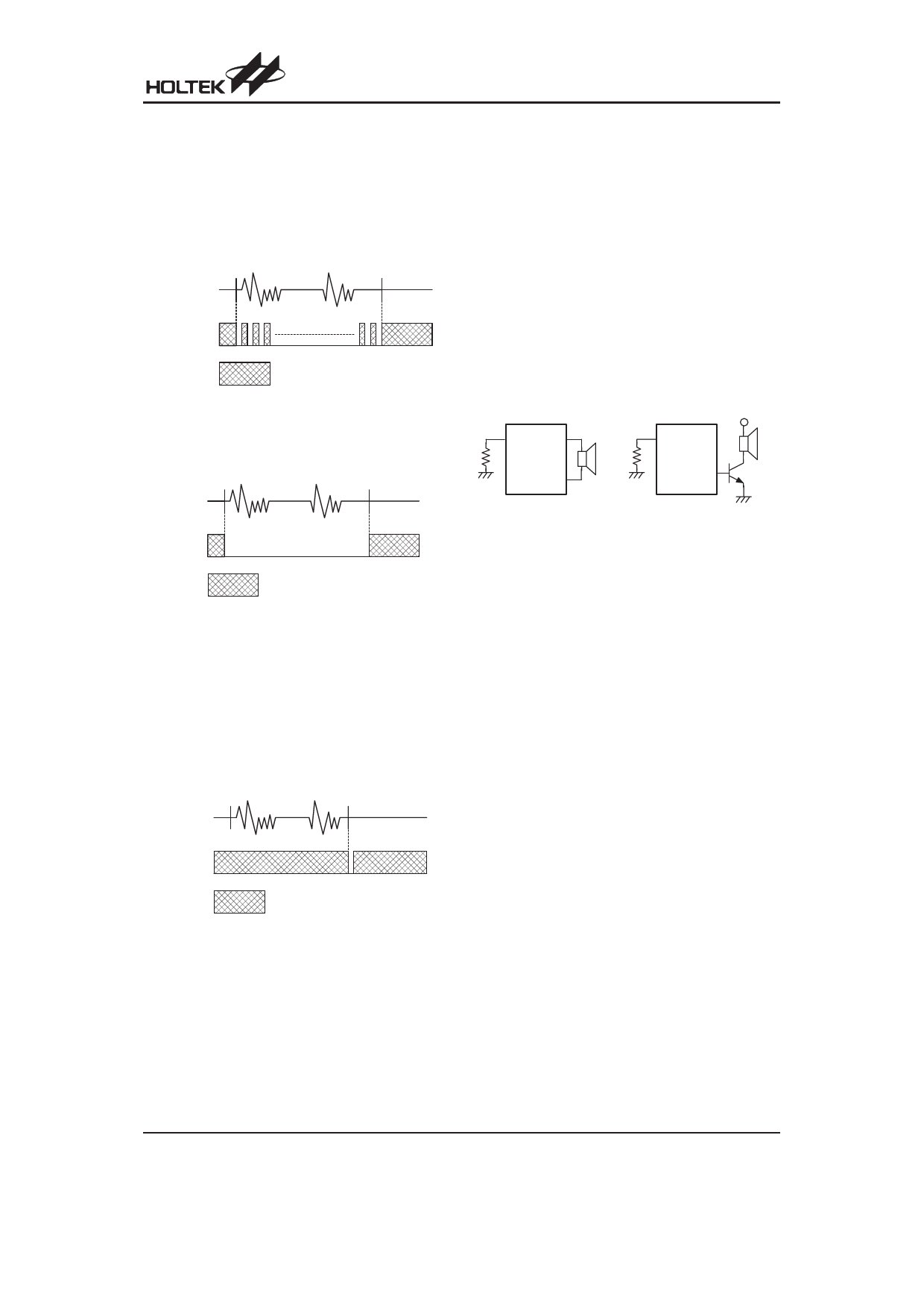
I/O2
The I/O2 pin is a PWM structure. It outputs voice signals
to drive a speaker through an external NPN transistor
when the chip is active. The OUT1 and OUT2 pins are
configured as PWM structure which can drive 8/16/32W
speaker directly.
An 8050 type transistor with hFE@150 is recommended
for an output driver.
V DD
R OSC O S C I O U T 1
R OSC O S C I
SPK
SPK
O U T2
O U T3
H T81X X X
H T81X X X
FLA G
: F lo a tin g
In addition to the above-stated output signals, FLAG1
can also generate one of the following signals by code
option:
¨ End-pulse output
When the voice output is completed, the FLAG1 pin
outputs an active low pulse. The pulse width can be
programmed depending on the customer¢s require-
ments.
The FLAG1 as well as FLAG2 pins are both floating
outputs when the chip is in the standby state.
AUD
FLA G
: F lo a tin g
Rev. 1.40
13
March 1, 2005
Share Link: 