L6563 データシートの表示(PDF) - STMicroelectronics
部品番号
コンポーネント説明
メーカー
L6563 Datasheet PDF : 37 Pages
| |||
Application information
L6563 - L6563A
The twice-mains-frequency (2·fL) ripple appearing across CFF is triangular with a peak-to-
peak amplitude that, with good approximation, is given by:
Equation 4
∆VFF
=
-------2---V-----M----U----L---T---p---k-------
1 + 4fLRFFCFF
where fL is the line frequency. The amount of 3rd harmonic distortion introduced by this
ripple, related to the amplitude of its 2·fL component, will be:
Equation 5
D3%
=
------------1----0---0--------------
2πfLRFFCFF
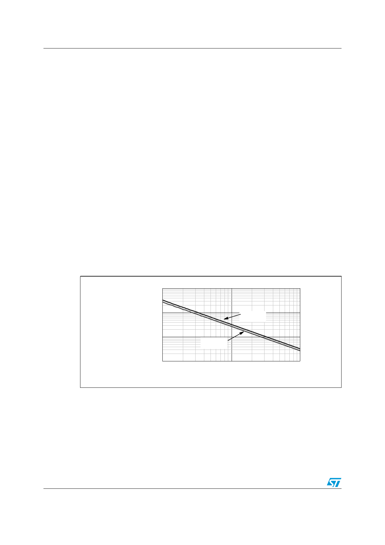
Figure 35 shows a diagram that helps choose the time constant RFF·CFF based on the
amount of maximum desired 3rd harmonic distortion. Always connect RFF and CFF to the
pin, the IC will not work properly if the pin is either left floating or connected directly to
ground.
Figure 35. RFF·CFF as a function of 3rd harmonic distortion introduced in the input
current
10
1
RFF· CFF [s]
0.1
0.01
0.1
f L= 50 Hz
fL=60 Hz
1
10
D3%
The dynamics of the voltage feedforward input is limited downwards at 0.5V (see Figure 34),
that is the output of the multiplier will not increase any more if the voltage on the VFF pin is
below 0.5V. This helps to prevent excessive power flow when the line voltage is lower than
the minimum specified value
20/37
Share Link: 