LA3430 データシートの表示(PDF) - SANYO -> Panasonic
部品番号
コンポーネント説明
メーカー
LA3430 Datasheet PDF : 12 Pages
| |||
LA3430
Specifications
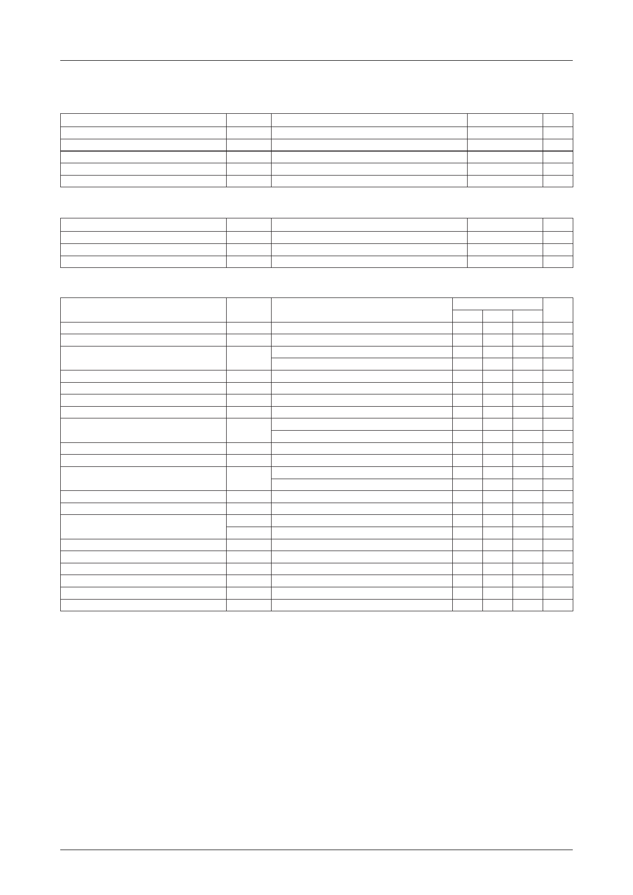
Absolute Maximum Ratings at Ta = 25˚C
Parameter
Maximum Supply Voltage
Lamp Driving Current
Allowable Power Dissipation
Operating Temperature
Storage Temperature
Symbol
VCC max
IL max
Pd max
Topr
Tstg
Ta≤45˚C
Conditions
Ratings
Unit
16 V
30 mA
520 mW
–20 to +70 ˚C
–40 to +125 ˚C
Operating Conditions at Ta = 25˚C
Parameter
Recommended Supply Voltage
Operating Voltage Range
Recommended Input Signal Voltage
Symbol
VCC
VCC op
Vi
Conditions
Ratings
Unit
10 V
6.5 to 13 V
200 to 300 mV
Operating Characteristics at Ta = 25˚C, VCC=10V, Vi=300mV, f=1kHz, L+R=90%, pilot=10%
Parameter
Symbol
Conditions
Ratings
Unit
min typ max
Quiescent Current
Icco No input
28
38 mA
Channel Separation
Sep
40
50
dB
Total Harmonic Distortion
THD
Monaural
Main
0.07
0.2 %
0.07
0.2 %
Lamp Lighting Level
Lamp Hysteresis
VL
L+R=90%, pilot=10%
hy
60
85 120 mV
3
6 dB
Capture Range
CR
±1
%
Output Signal Level
Signal to Noise Ratio
VO
Sub
Rg=20kΩ
S/N
Rg=10kΩ
150 215 300 mV
68
74
dB
70
78
dB
Input Resistance (Pin 2)
ri
20
kΩ
SCA Rejection
SCA rej
80
dB
Allowable Input Voltage
THD=1%, Rg=20kΩ
Vi
THD=1%, Rg=20kΩ
700 900
mV
450
mV
SNC Output Attenuation
Att SNC V8=0.6V, L–R=90%, pilot=10%
–8.5 –3.0 –0.3 dB
SNC Output Voltage
HCC Output Attenuation
VO sub
Att HCC1
Att HCC2
V8=0.1V, L–R=90%, pilot=10%
V7=0.6V, L+R=90%, pilot=10%
V7=1V, L+R=90%, pilot=10%
5 mV
–15.0 –6.0 –0.5 dB
–2.0
0 dB
Ripple Rejection of Power Supply
Rr
35
dB
VCO Stop Voltage
7.3
V
Channel Balance
0.5
1.5 dB
Pilot Cancel
20
27
dB
Stereo Lamp Current
Minimum stereo operating current
1.0
mA
Saturation Voltage (Pin 10)
IL=10mA
1.0
V
No.1408–2/12
Share Link: 