LTC6801HG-TRPBF(RevC) データシートの表示(PDF) - Linear Technology
部品番号
コンポーネント説明
メーカー
LTC6801HG-TRPBF Datasheet PDF : 28 Pages
| |||
LTC6801
APPLICATIONS INFORMATION
READING EXTERNAL TEMPERATURE PROBES
The LTC6801 includes two channels of ADC input, VTEMP1
and VTEMP2, that are intended to monitor thermistors
(tempco about –4%/°C generally) or diodes (–2.2mV/°C
typical) located within the cell array. Sensors can be
powered directly from VREF as shown in Figure 9 (up to
30µA typical).
The temperature measurement inputs (VTEMP1, VTEMP2) of
the LTC6801 are comparator input channels with a voltage
threshold of one-half VREF. Input voltages above half VREF
are considered good. Voltages below the one-half VREF
threshold are considered a fault condition. The inputs
may be used in combination with resistors, thermistors,
or diodes to sense both an upper and lower temperature
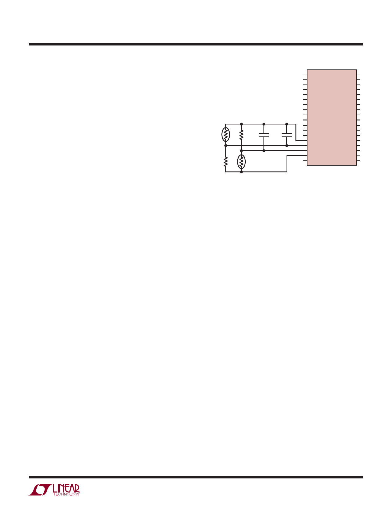
limit. Figure 9, Figure 10 and Figure 11 illustrate some
possibilities. To ignore these inputs simply connect VTEMP1
and VTEMP2 to VREF. A filtering capacitor to V– is recom-
mended to minimize the error caused by the approximately
700k input impedance of the ADC.
For sensors that require higher drive currents, a buffer
amplifier may be used as shown in Figure 10. Power for
the sensor is actually sourced indirectly from the VREG pin
in this case. Probe loads up to about 1mA maximum are
supported in this configuration. Since VREF is shut down
while the LTC6801 is idle between measurement cycles,
the thermistor drive is also shut off and thus power dis-
sipation is minimized. Since VREG remains always-on, the
buffer op amp (LT6003 shown) is selected for its ultralow
current consumption (10µA).
500k
NTC
B = 4567
100k
1150k
1µF
1µF
100k
NTC
B = 4250
V+
OV1
C12
OV0
C11
UV1
C10
UV0
C9
HYST
C8
CC1
C7 LTC6801 CC0
C6
SLT
C5
SLTOK
C4
DC
C3
EOUT
C2
EOUT
C1
SIN
V–
SIN
VTEMP1
SOUT
VTEMP2
SOUT
VREF
EIN
VREG
EIN
6801 F11
Figure 11. Sensing Both Upper and Lower Temperature
Thresholds. This Example Monitors a –20°C to +60°C Window
Detector. The Thermistors Should Be in Close Proximity
For circuits that include filtering capacitance, note that
only the fastest DC setting (VREG connection) will keep
VREF steady and allow the VTEMP voltages to settle. To use
the lower power DC settings, VREF must be buffered (see
Figure 10), so that a low impedance is presented to the
ADC, with a time constant of no more than about 1ms.
ADVANTAGES OF DELTA-SIGMA ADCs
The LTC6801 employs a delta-sigma analog to digital
converter for voltage measurement. The architecture of
delta-sigma converters can vary considerably, but the
common characteristic is that the input is sampled many
times over the course of a conversion and then filtered or
averaged to produce the digital output code.
For more information www.linear.com/LTC6801
6801fc
21
Share Link: 