M29DW323DB90N6F データシートの表示(PDF) - STMicroelectronics
部品番号
コンポーネント説明
メーカー
M29DW323DB90N6F
STMicroelectronics

M29DW323DB90N6F Datasheet PDF : 49 Pages
| |||
M29DW323DT, M29DW323DB
APPENDIX D. BLOCK PROTECTION
Block protection can be used to prevent any oper-
ation from modifying the data stored in the memo-
ry. The blocks are protected in groups, refer to
Appendix A, Tables 21 and 22 for details of the
Protection Groups. Once protected, Program and
Erase operations within the protected group fail to
change the data.
There are three techniques that can be used to
control Block Protection, these are the Program-
mer technique, the In-System technique and Tem-
porary Unprotection. Temporary Unprotection is
controlled by the Reset/Block Temporary Unpro-
tection pin, RP; this is described in the Signal De-
scriptions section.
Programmer Technique
The Programmer technique uses high (VID) volt-
age levels on some of the bus pins. These cannot
be achieved using a standard microprocessor bus,
therefore the technique is recommended only for
use in Programming Equipment.
To protect a group of blocks follow the flowchart in
Figure 20, Programmer Equipment Block Protect
Flowchart. To unprotect the whole chip it is neces-
sary to protect all of the groups first, then all
groups can be unprotected at the same time. To
unprotect the chip follow Figure 21, Programmer
Equipment Chip Unprotect Flowchart. Table 30,
Programmer Technique Bus Operations, gives a
summary of each operation.
The timing on these flowcharts is critical. Care
should be taken to ensure that, where a pause is
specified, it is followed as closely as possible. Do
not abort the procedure before reaching the end.
Chip Unprotect can take several seconds and a
user message should be provided to show that the
operation is progressing.
In-System Technique
The In-System technique requires a high voltage
level on the Reset/Blocks Temporary Unprotect
pin, RP. This can be achieved without violating the
maximum ratings of the components on the micro-
processor bus, therefore this technique is suitable
for use after the memory has been fitted to the sys-
tem.
To protect a group of blocks follow the flowchart in
Figure 22, In-System Block Protect Flowchart. To
unprotect the whole chip it is necessary to protect
all of the groups first, then all the groups can be
unprotected at the same time. To unprotect the
chip follow Figure 23, In-System Chip Unprotect
Flowchart.
The timing on these flowcharts is critical. Care
should be taken to ensure that, where a pause is
specified, it is followed as closely as possible. Do
not allow the microprocessor to service interrupts
that will upset the timing and do not abort the pro-
cedure before reaching the end. Chip Unprotect
can take several seconds and a user message
should be provided to show that the operation is
progressing.
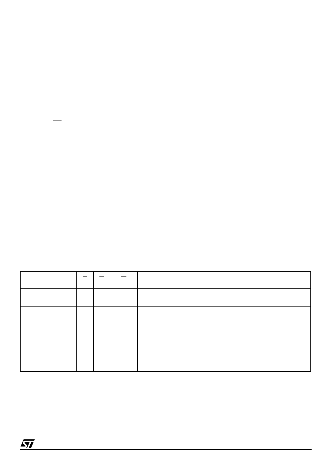
Table 30. Programmer Technique Bus Operations, BYTE = VIH or VIL
Operation
EG
W
Address Inputs
A0-A20
Block (Group)
Protect(1)
VIL VID VIL Pulse
A9 = VID, A12-A20 Block Address
Others = X
Chip Unprotect
VID VID VIL Pulse
A9 = VID, A12 = VIH, A15 = VIH
Others = X
Block (Group)
Protection Verify
VIL VIL
A0 = VIL, A1 = VIH, A6 = VIL, A9 = VID,
VIH
A12-A20 Block Address
Others = X
Block (Group)
Unprotection Verify
VIL VIL
A0 = VIL, A1 = VIH, A6 = VIH, A9 = VID,
VIH
A12-A20 Block Address
Others = X
Note: 1. Block Protection Groups are shown in Appendix A, Tables 21 and 22.
Data Inputs/Outputs
DQ15A–1, DQ14-DQ0
X
X
Pass = XX01h
Retry = XX00h
Retry = XX01h
Pass = XX00h
43/49
Share Link: