MAX1820 データシートの表示(PDF) - Maxim Integrated
部品番号
コンポーネント説明
メーカー
MAX1820 Datasheet PDF : 18 Pages
| |||
WCDMA Cellular Phone 600mA
Buck Regulators
Output Capacitor Selection
The output capacitor is required to keep the output volt-
age ripple small and to ensure regulation control loop
stability. The output capacitor must have low imped-
ance at the switching frequency. Ceramic capacitors
are recommended. The output ripple is approximately:
VRIPPLE ≈ LIR ✕ IOUT(MAX)
( ) ⎡
× ⎢ESR +
1
⎤
⎥
⎣⎢
2 × ƒOSC × COUT ⎦⎥
See the Compensation Design section for a discussion
of the influence of output capacitance and ESR on reg-
ulation control-loop stability.
The capacitor voltage rating must exceed the maximum
applied capacitor voltage. Consult the manufacturer’s
specifications for proper capacitor derating. Avoid Y5V
and Z5U dielectric types due to their huge voltage and
temperature coefficients of capacitance and ESR.
PC Board Layout and Routing
High switching frequencies and large peak currents
make PC board layout a very important part of design.
Good design minimizes excessive EMI on the feedback
paths and voltage gradients in the ground plane, both
of which can result in instability or regulation errors.
Connect the inductor, input filter capacitor, and output
filter capacitor as close together as possible, and keep
their traces short, direct, and wide. Connect their
ground pins at a single common node in a star-ground
configuration. The external voltage-feedback network
should be very close to the FB pin, within 0.2in (5mm).
Keep noisy traces (from the LX pin, for example) away
from the voltage-feedback network; also, keep them
separate, using grounded copper. Connect GND and
PGND at a single point, as close as possible to the
MAX1820/MAX1821. The MAX1820/MAX1821 evalua-
tion kit manual illustrates an example PC board layout
and routing scheme.
UCSP Package Consideration
For general UCSP package information and PC layout
considerations, refer to the Maxim Application Note
(Wafer-Level Ultra-Chip-Board-Scale Package).
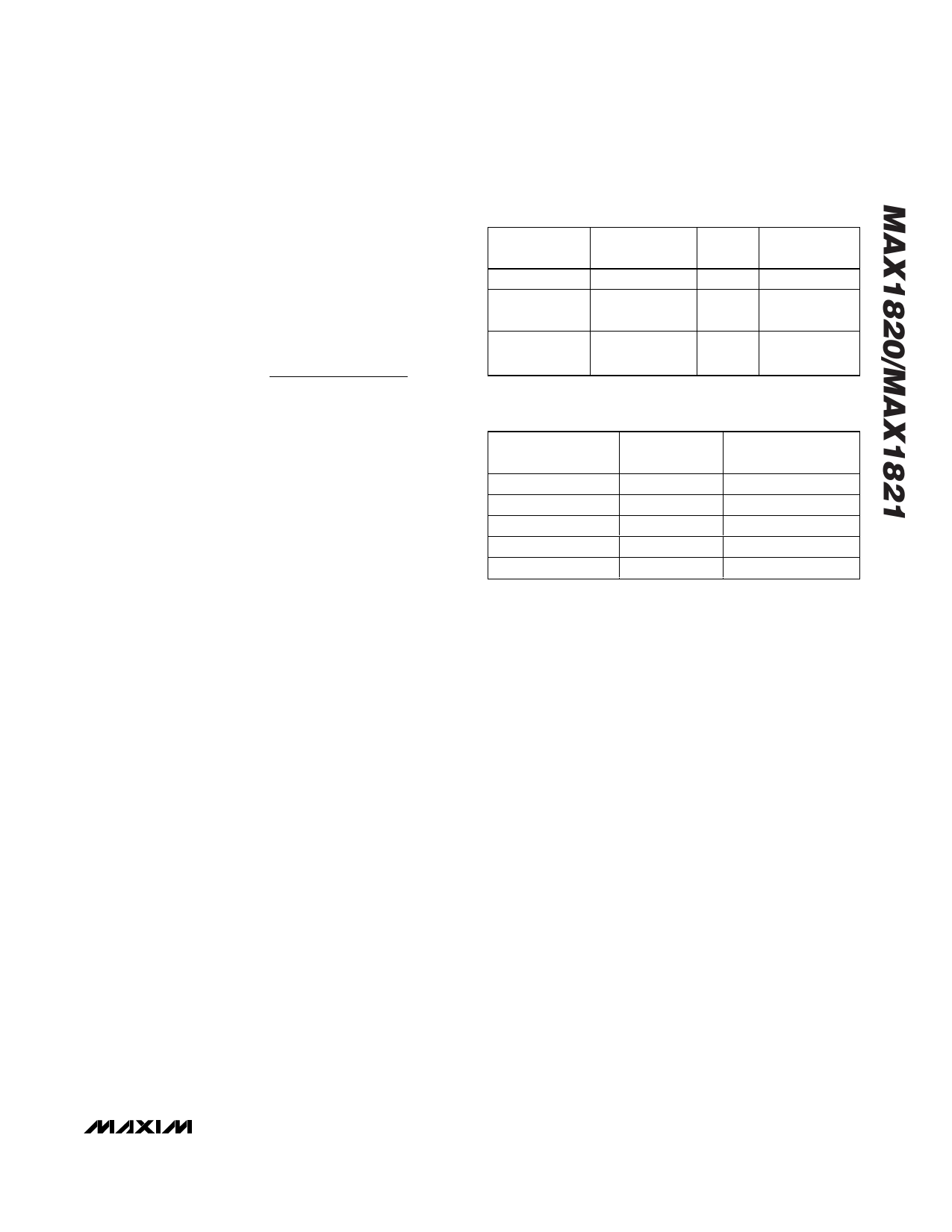
Table 2. Capacitor Selection
CAPACITOR
CBATT
COUT
(MAX1820)
COUT
(MAX1821)
CAPACITOR
VALUE (µF)
4.7 to 10
2.2 to 4.7
4.7 to 10
ESR
(mΩ)
<150
<50
<150
CAPACITOR
TYPE
Ceramic
Ceramic
Ceramic
Table 3. Component Manufacturers
MANUFACTURER
Coilcraft
Kemet
Panasonic
Sumida
Taiyo Yuden
USA PHONE
NUMBER
847-639-6400
408-986-0424
847-468-5624
847-956-0666
408-573-4150
WEBSITE
www.coilcraft.com
www.kemet.com
www.panasonic.com
www.sumida.com
www.t-yuden.com
______________________UCSP Reliability
The chip-scale package (UCSP) represents a unique
packaging form factor that may not perform equally to a
packaged product through traditional mechanical relia-
bility tests. UCSP reliability is integrally linked to the
user’s assembly methods, circuit board material, and
usage environment. The user should closely review
these areas when considering use of a UCSP package.
Performance through Operating Life Test and Moisture
Resistance remains uncompromised as it is primarily
determined by the wafer-fabrication process.
Mechanical stress performance is a greater considera-
tion for a UCSP package. UCSPs are attached through
direct solder contact to the user’s PC board, foregoing
the inherent stress relief of a packaged-product lead
frame. Solder joint contact integrity must be consid-
ered. Information on Maxim’s qualification plan, test
data, and recommendations are detailed in the UCSP
application note, which can be found on Maxim’s website,
www.maxim-ic.com.
____________________Chip Information
TRANSISTOR COUNT: 2722
______________________________________________________________________________________ 15
Share Link: 