MB91354A データシートの表示(PDF) - Fujitsu
部品番号
コンポーネント説明
メーカー
MB91354A Datasheet PDF : 111 Pages
| |||
MB91350A Series
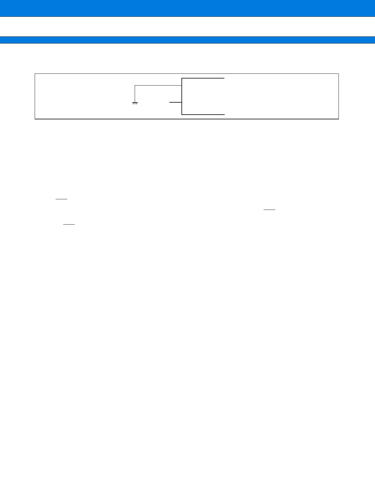
• Notes on not using the sub clock
When no oscillator is connected to the X0A and X1A pins, pull down the X0A pin and open the X1A pin.
X0
OPEN
X1
MB91350A
• Treatment of NC and OPEN pins
Pins marked as NC and OPEN must be left open-circuit.
• Mode pins (MD0 to MD2)
These pins should be connected directly to VCC or VSS.
To prevent the device erroneously switching to test mode due to noise, design the printed circuit board such that
the distance between the mode pins and VCC or VSS is as short as possible and the connection impedance is low.
• Operation at start-up
The INIT pin must be at Low level when the power supply is turned on.
Immediately after the power supply is turned on, hold the Low level input to the INIT pin for the settling time
required for the oscillator circuit to take the oscillation stabilization wait time for the oscillator circuit. (For INIT
via the INIT pin, the oscillation stabilization wait time setting is initialized to the minimum value.)
• About oscillation input at power on
When turning the power on, maintain clock input until the device is released from the oscillation stabilization
wait state.
• Caution on Operations during PLL Clock Mode
Even if the oscillator comes off or the clock input stops with the PLL clock selected for this microcontroller, the
microcontroller may continue to operate at the free-running frequency of the PLL’s internal self-oscillating oscil-
lator circuit. Performance of this operation, however, cannot be guaranteed.
• External bus setting
This model guarantees an external bus frequency of 25 MHz.
Setting the base clock frequency to 50 MHz with DIVR1 (external bus base clock division setting register)
initialized sets the external bus frequency also to 50 MHz. Before changing the base clock frequency, set the
external bus frequency not exceeding 25 MHz.
• MCLK and SYSCLK
MCLK and SYSCLK has a difference that MCLK stops in SLEEP/STOP mode but SYSCLK stops only in STOP
mode. Use either depending on each application.
Upon initialization, MCLK becomes invalid (PORT) and SYSCLK becomes valid. To use MCLK, set the port
function register (PFR) to select the use of that clock.
• Pull-up control
Connecting a pull-up resistor to the pin serving as an external bus pin cannot a guarantee the “■ ELECTRICAL
CHARACTERISTICS 4. AC Characteristics (4) Normal Bus Access Read/Write Operation, (5) Multiplex Bus
Access Read/Write operation and (7) Hold Timing”.
Even the port for which a pull-up resistor has been set is invalid in stop mode with HIZ = 1 or in hardware standby
mode.
18
Share Link: 