T-51382D064J-FW-P-AC データシートの表示(PDF) - Optrex Corporation
部品番号
コンポーネント説明
メーカー
T-51382D064J-FW-P-AC Datasheet PDF : 24 Pages
| |||
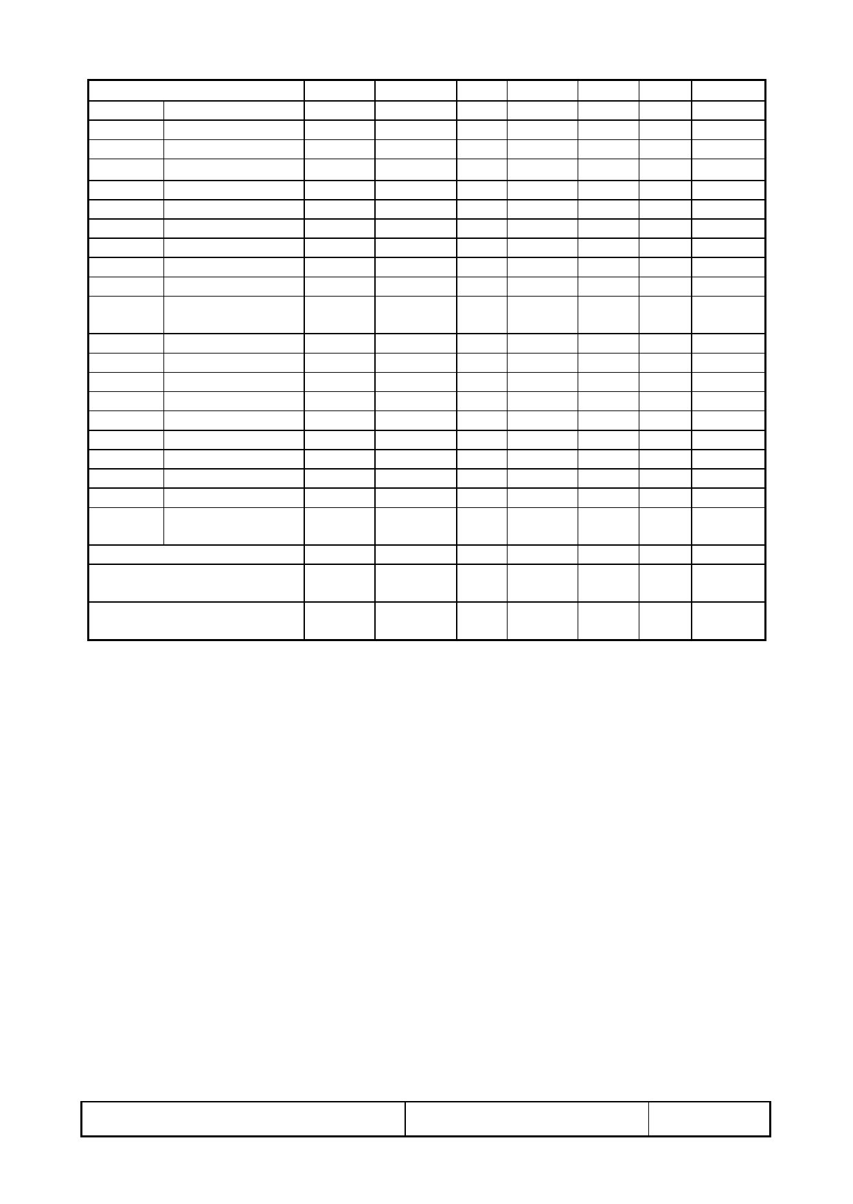
7-3) Input / Output signal timing chart
Parameters
Symbol Format Min. Typ. Max. Unit Note
Frequency
Fc=1/Tc All
25.175
MHz Note 7-3
Clock High Time
Tckh
All
10
ns
Low Time
Tckl
All
10
ns
Periodic = Line
Thp
All
31.778
µs Note 7-3
Hsync
800 1024 clock Note 7-3
Pulse Width
Thpw
All
2
96
200 clock
Back Porch
Thbp
All
2
48
64 clock
VGA-480 515 525 1024 line Note 7-3
Periodic = Frame Tvp VGA-400 447 449 1024 line Note 7-3
VGA-350 447 449 1024 line Note 7-3
Vsync
Freedom
1024 line
Mode
Pulse Width
Tvpw
All
1
2
line
Back Porch
Tvbp
All
1
64 line
Data Setup Time
Tds
All
10
ns
Hold Time
Tdh
All
10
ns
Periodic = Line
Tep
All
800 1024 clock
Pulse Width (H)
Tepw
All
2
640 800 clock
DENB
VGA-480 480 480
line
Display Line No(V) Tvd VGA-400 400 400
line
VGA-350 350 350
line
Freedom
480
line
Mode
Horizontal Display Periodic
Thd
All
640 640 640 clock
Hsync-CLK
Thc
All
10
Tc-10 ns
Phase Difference
Vsync-Hsync
Tvh
All
1
Thp-1 clock
Phase Difference
Note 7-3: Tc is the period of sampling clock. In case of low-frequency, the image-flicker may occur.
T-51382D064J-FW-P-AC (AC) No. 2002-0168
OPTREX CORPORATION
Page 7/24
Share Link: 