PCA84C822AP データシートの表示(PDF) - Philips Electronics
部品番号
コンポーネント説明
メーカー
PCA84C822AP Datasheet PDF : 24 Pages
| |||
Philips Semiconductors
8-bit microcontrollers for
remote control transmitters
15 APPLICATION INFORMATION
Product specification
PCA84C122; 222; 422; 622; 822
100 Ω
P00
V DD
P01
P02
XTAL1
P03
P04
XTAL2
P05
P06
T0 / INT
P07
84C122A T1
P10
P11
P12
27 mA
P13
OUT
P14
P15
RESET
P16
P17
VSS
3.0 V
MCD252
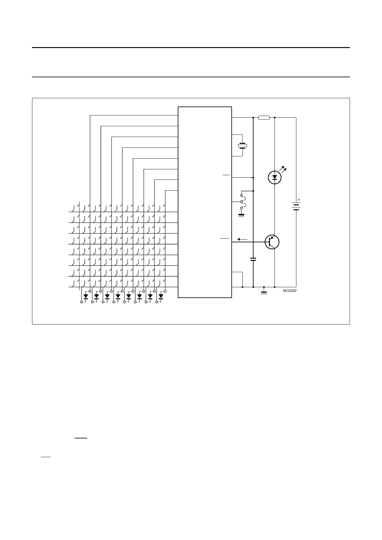
Fig.12 PCA84C122A Remote control transmitter application.
Figure 12 shows the main application of the PCA84C122
as a remote control transmitter. Each key of the transmitter
keypad represents a specific command. The keys are in an
orderly matrix with each key connected between an I/O
line of Port 0 and an I/O line of Port 1.
The lines of Port 0 are designated ‘scan’ (output) lines, and
the lines of Port 1 are ‘sense’ (input) lines.
By making each scan line a logic 0 in turn, and each time
looking at the sense lines, the depressed key is detected.
The corresponding command code is determined by using
a software look-up table. This code together with the
system address is sent according to a coding scheme or
protocol (e.g. RC-5). The pulses that are generated are
available at the OUT pin. This pin drives the output
transistor, which provides the current for the IR-LED.
T0/INT is not used and therefore connected to VDD. T1 is
used for system or option selection, therefore a jumper can
be connected to VDD or ground.
When more options must be selected, this can be done in
different ways as illustrated in the following two examples:
1. When the number of keys is sufficiently low a scan line
can be spared. This scan line may be used to connect
a jumper wire to one of the sense lines. Normally the
scan line should be logic 1. When this line is set to
logic 0 the option setting can be read from the sense
lines.
2. By connecting diodes between one sense line and a
number of scan lines (see Fig.12). If necessary these
diodes can be placed parallel to the keys. When the
sense line is set to logic 0 (acts as scan line), the
option setting can be read from the scan lines (which
act as sense lines and should be set to logic 1
beforehand).
For the oscillator a crystal or ceramic resonator may be
used. A resistor in series with the supply, limits the reverse
current through the IC in the event of the supply voltage
being reversed (i.e. wrong insertion of batteries).
1995 May 01
14
Share Link: 