ATMEGA103 データシートの表示(PDF) - Atmel Corporation
部品番号
コンポーネント説明
メーカー
ATMEGA103 Datasheet PDF : 10 Pages
| |||
ATmega603(L) and ATmega103(L)
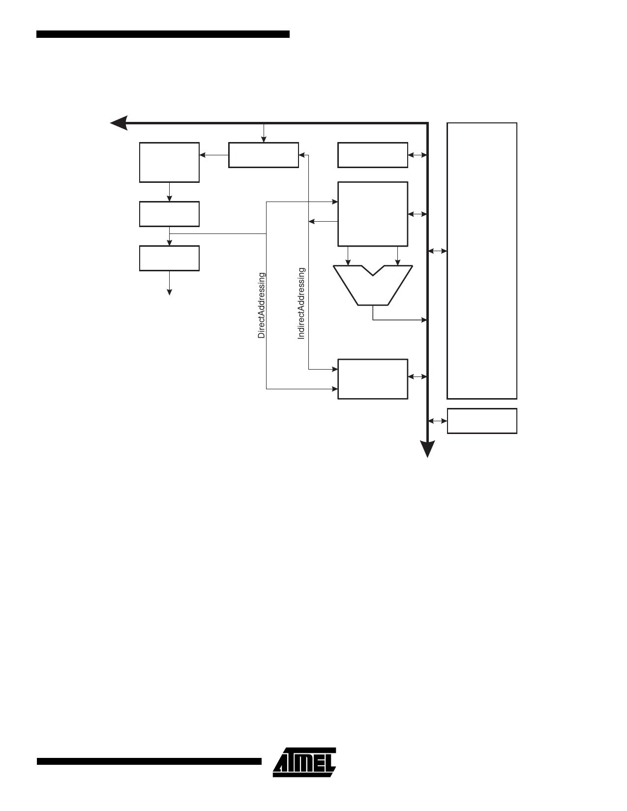
Figure 4. The ATmega603/103 AVR Enhanced RISC Architecture
AVR ATmega603/103 Architecture
Data Bus 8-bit
32K/64K x 16
Program
Memory
Instruction
Register
Instruction
Decoder
Control Lines
Program
Counter
Status
and Test
32 x 8
General
Purpose
Registers
ALU
Peripherals
4K x 8
Data
SRAM
2K/4K x 8
EEPROM
The AVR uses a Harvard architecture concept - with sepa-
rate memories and buses for program and data. The pro-
gram memory is executed with a single level pipelining.
While one instruction is being executed, the next instruction
is pre-fetched from the program memory. This concept
enables instructions to be executed in every clock cycle.
The program memory is in-system programmable Flash
memory. With a few exceptions, AVR instructions have a
single 16-bit word format, meaning that every program
memory address contains a single 16-bit instruction.
During interrupts and subroutine calls, the return address
program counter (PC) is stored on the stack. The stack is
effectively allocated in the general data SRAM, and conse-
quently the stack size is only limited by the total SRAM size
and the usage of the SRAM. All user programs must initial-
ize the SP in the reset routine (before subroutines or inter-
rupts are executed). The 16-bit stack pointer SP is
read/write accessible in the I/O space.
The 4000 bytes data SRAM can be easily accessed
through the five different addressing modes supported in
the AVR architecture.
A flexible interrupt module has its control registers in the
I/O space with an additional global interrupt enable bit in
the status register. All the different interrupts have a sepa-
rate interrupt vector in the interrupt vector table at the
beginning of the program memory. The different interrupts
have priority in accordance with their interrupt vector posi-
tion. The lower the interrupt vector address, the higher the
priority.
The memory spaces in the AVR architecture are all linear
and regular memory maps.
The General Purpose Register File
Figure 5 shows the structure of the 32 general purpose
working registers in the CPU.
5
Share Link: 