M80C186 データシートの表示(PDF) - Intel
部品番号
コンポーネント説明
メーカー
M80C186 Datasheet PDF : 59 Pages
| |||
M80C186
270500 – 13
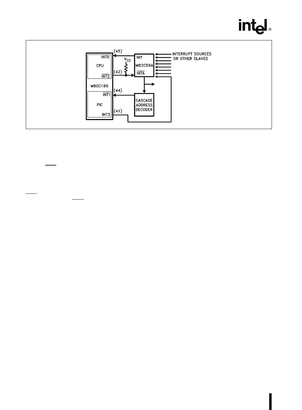
Figure 33 Slave Mode Interrupt Controller Connections
Correct master-slave interface requires decoding of
the slave addresses (CAS0-2) Slave M82C59As do
this internally Because of pin limitations the
M80C186 slave address will have to be decoded ex-
ternally INT1 (Pin 44) is used as a slave-select in-
put Note that the slave vector address is transferred
internally but the READY input must be supplied ex-
ternally
Specific End-of-Interrupt
In slave mode the specific EOI command operates
to reset an in-service bit of a specific priority The
user supplies a 3-bit priority-level value that points to
an in-service bit to be reset The command is exe-
cuted by writing the correct value in the Specific EOI
register at offset 22H
INT2 (Pin 42) is used as an acknowledge output
suitable to drive the INTA input of an M82C59A
Interrupt Nesting
Slave mode operation allows nesting of interrupt re-
quests When an interrupt is acknowledged the pri-
ority logic masks off all priority levels except those
with equal or higher priority
Vector Generation in the Slave Mode
Vector generation in slave mode is exactly like that
of an M82C59A slave The interrupt controller gen-
erates an 8-bit vector which the CPU multiplies by
four and uses as an address into a vector table The
significant five bits of the vector are user-program-
mable while the lower three bits are generated by
the priority logic These bits represent the encoding
of the priority level requesting service The signifi-
cant five bits of the vector are programmed by writ-
ing to the Interrupt Vector register at offset 20H
Interrupt Controller Registers
in the Slave Mode
All control and command registers are located inside
the internal peripheral control block Figure 34
shows the offsets of these registers
End-of-Interrupt Register
The end-of-interrupt register is a command register
which can only be written The format of this register
is shown in Figure 35 It initiates an EOI command
when written by the M80C186 CPU
The bits in the EOI register are encoded as follows
Lx Encoded value indicating the priority of the IS
bit to be reset
38
Share Link: 