UPSD3233 データシートの表示(PDF) - STMicroelectronics
部品番号
コンポーネント説明
メーカー
UPSD3233
STMicroelectronics

UPSD3233 Datasheet PDF : 170 Pages
| |||
uPSD3234A, uPSD3234BV, uPSD3233B, uPSD3233BV
REVISION HISTORY
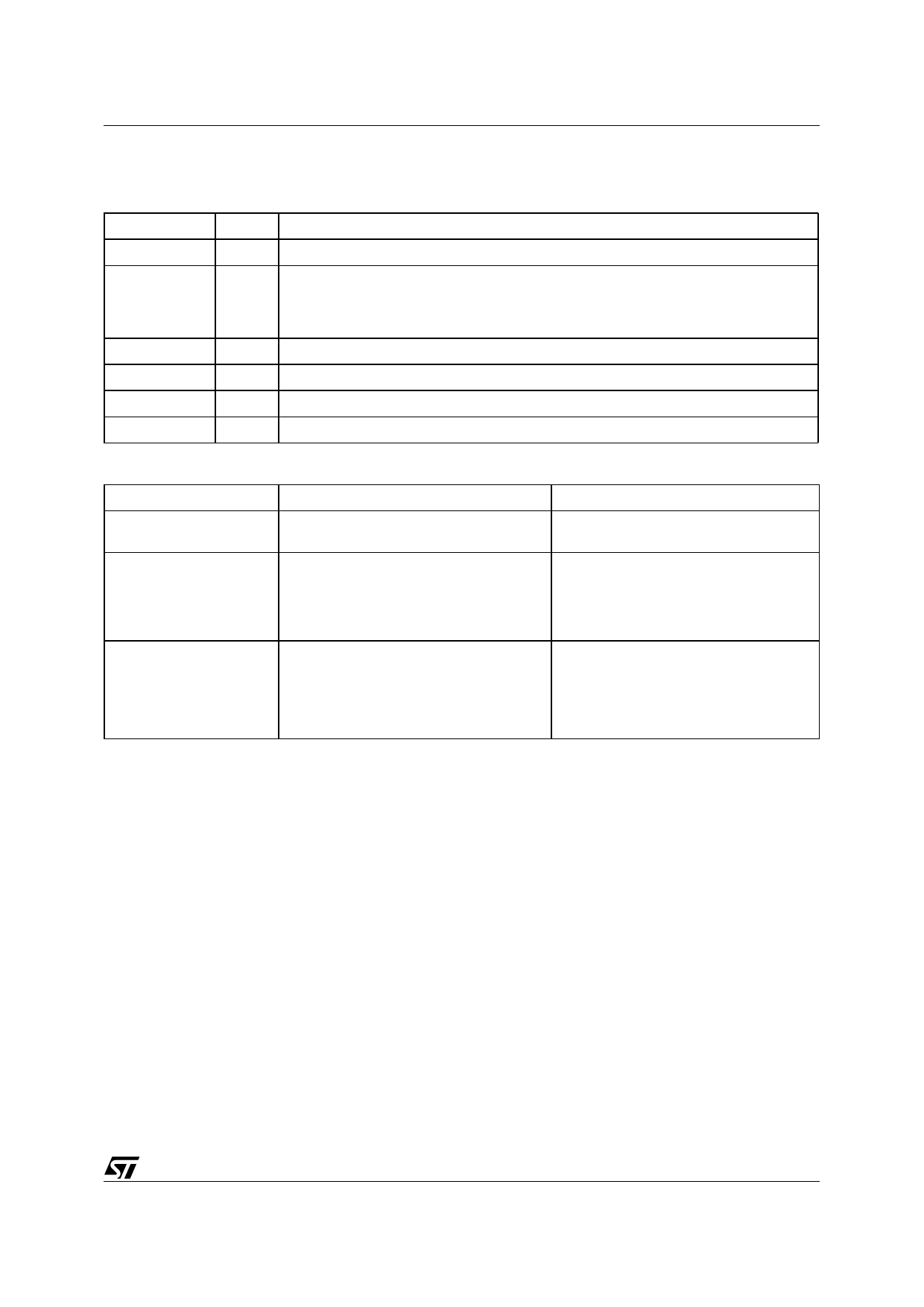
Table 150. Document Revision History
Date
Version
Revision Details
November 2002 1.0 First Issue
27-Feb-03
Updates: product information (Figure 3, 4, Table 1, 2); port information (Figure 17, 18,
1.1
Table 30); interface information (Figure 30, Table 44); remove programming guide; PSD
Module information (Figure 50, 51, Table 85); PLD information (Figure 58, 59, Table 91,
92, 93); electrical characteristics (Table 118, 119, 135, 136)
02-Sep-03
1.2 Updated references for Product Catalog
04-Feb-04
2.0 Reformatted; corrected mechanical dimensions (Table 148)
05-Jul-04
3.0 Reformatted; added EMC characteristics (Table 109, 110, 111)
04-Nov-04
4.0 Updates according to data brief change request (Figure 3, 4; Table 1, 2, 116)
Table 151. Device Functional Change History
Functional Change
After Date Code 0242
Date Code 0242 and before
PWM Block
An 8-bit, Programmable PWM 4 channel
and the associated registers are added.
Only PWM0-PWM3 channels are
available.
DDC SRAM Mapping
When DDC is disabled, the data space
FF00h-FFFFh assigned to DDC SRAM is
available for external data mapping. The
SWENB Bit definition in the DDCON
Register is modified.
Data space FF00h-FFFFh is dedicated to
DDC SRAM.
USB Reset Function
1. Option to block USB generated reset
from resetting the MCU/PSD modules.
2. Allow USB Reset Flag (RSTF) to
USB-generated reset always resets both,
interrupt MCU.
the USB and the MCU/PSD modules.
3. Add RSTE and RSTFIE Bits to the
UIEN Interrupt Enable Register.
Note: Date Code is the 6th to the 9th digit of the Trace Code on top of the device.
169/170
Share Link: