FSFR1800HSL データシートの表示(PDF) - Unspecified
部品番号
コンポーネント説明
メーカー
FSFR1800HSL Datasheet PDF : 16 Pages
| |||
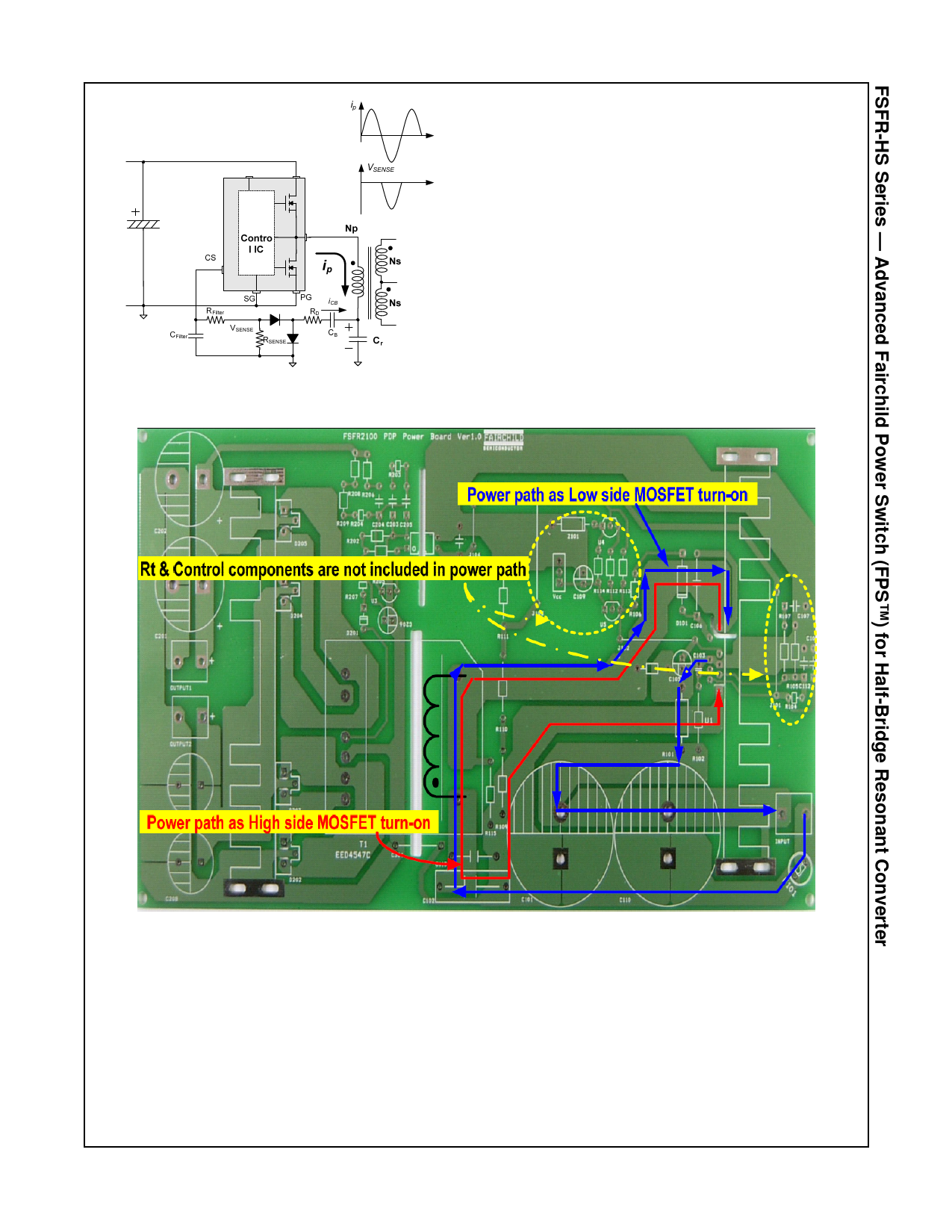
Figure 29. Capacitive Sensing
9. PCB Layout Guidelines: Duty imbalance problems
may occur due to the radiated noise from the main
transformer, the inequality of the secondary side
leakage inductances of main transformer, and so on.
This is one of the reasons that the control components
in the vicinity of the RT pin are enclosed by the primary
current flow pattern on PCB layout. The direction of the
magnetic field on the components caused by the
primary current flow is changed when the high- and
low-side MOSFET turn on by turns. The magnetic fields
with opposite directions induce a current through, into,
or out of the RT pin, which makes the turn-on duration
of each MOSFET different. It is strongly recommended
to separate the control components in the vicinity of the
RT pin from the primary current flow pattern in the PCB
layout. Figure 30 shows an example for a duty-
balanced case.
Figure 30. Example of Duty Balancing
© 2011 Fairchild Semiconductor Corporation
FSFR1800 / FSFR1700-HS • Rev.1.0.1
13
www.fairchildsemi.com
Share Link: 