ATT3042 データシートの表示(PDF) - Unspecified
部品番号
コンポーネント説明
メーカー
ATT3042 Datasheet PDF : 80 Pages
| |||
Data Sheet
February 1997
ATT3000 Series Field-Programmable Gate Arrays
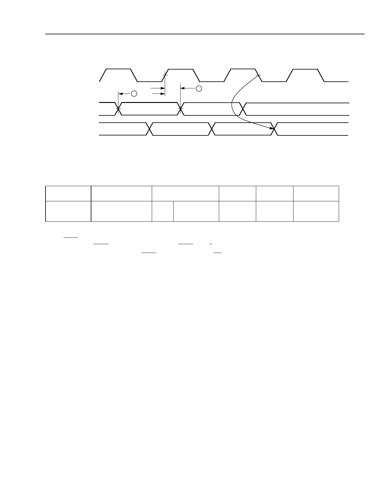
Electrical Characteristics (continued)
CCLK
(OUTPUT)
SERIAL DIN
SERIAL DOUT
(OUTPUT)
1 TDSCK
2 TCKDS
Figure 36. Master Serial Mode Switching Characteristics
5-3127(F).a
Table 26. Master Serial Mode Switching Characteristics
Signal
Description
Symbol
Min
Max
Unit
CCLK
Data-in Setup
1
TDSCK
60
—
ns
Data-in Hold
2
TCKDS
0
—
ns
Notes:
At powerup, VCC must rise from 2.0 V to VCC minimum in less than 25 ms. If this is not possible, configuration can be delayed by
holding RESET low until VCC has reached 4.0 V. A very long VCC rise time of >100 ms, or a nonmonotonically rising VCC may require
a >1 µs high level on RESET, followed by >6 µs low level on RESET and D/P after VCC has reached 4.0 V.
Configuration can be controlled by holding RESET low with or until after the INIT of all daisy-chain slave mode devices is high.
Master serial mode timing is based on slave mode testing.
Lucent Technologies Inc.
63
Share Link: 