HM6P5331 データシートの表示(PDF) - Hynix Semiconductor
部品番号
コンポーネント説明
メーカー
HM6P5331 Datasheet PDF : 10 Pages
| |||
PRELIMINARY
Powerdown Operation
Synchronous and asynchronous powerdown modes are both available. Synchronously powerdown occurs if the respective
loop’s R18 bit (Do High Z State) is LOW when its N20 bit (Powerdown) becomes HI. Asynchronous powerdown occurs if
the loop’s R18 bit is HI when its N20 bit becomes HI. In the synchronous powerdown mode, the powerdown function is
gated by the charge pump to prevent unwanted frequency jumps. Once the powerdown program bit N20 is loaded, the
part will go into powerdown mode when the charge pump reaches a High Z condition. In the asynchronous powerdown
mode, the device powers down immediately after the LE pin latches in a HI condition on the powerdown bit N20. Activation
of either the IF or RF PLL powerdown conditions in either synchronous or asynchronous modes forces the respective
loop’s R and N dividers to their load state condition and debiasing of its respective fin input to a high impedance state. The
oscillator circuitry function does not become disabled until both IF and RF powerdown bits are activated. The control
register remains active and capable of loading and latching data during all of the powerdown modes. The device returns to
an actively powered up condition in either synchronous or asynchronous modes immediately upon LE latching LOW data
into bit N20.
Powerdown Mode Select Table
R18 N20
0
0
1
0
0
1
1
1
Powerdown Status
PLL Active
PLL Active (Charge Pump High Z State)
Synchronous Powerdown Initiated
Asynchronous Powerdown Initiated
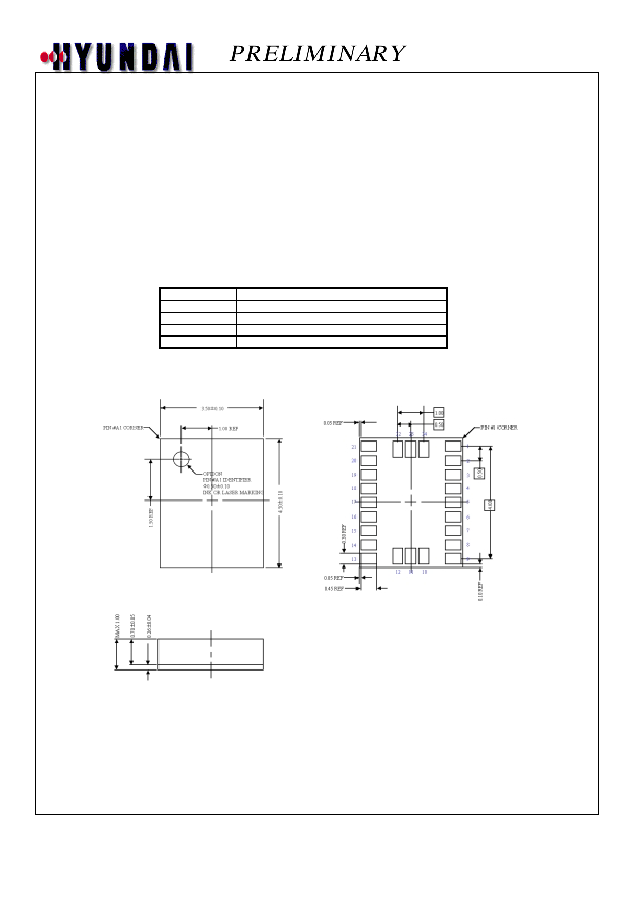
Physical Dimensions (unit : )
Leadless Grid Array Package
Share Link: 