LC5824 データシートの表示(PDF) - SANYO -> Panasonic
部品番号
コンポーネント説明
メーカー
LC5824 Datasheet PDF : 24 Pages
| |||
LC5824, LC5823, LC5822
Improved I/O Functions
• External interrupt pins
• Input pins that can clear halt mode:
10 pins (maximum)
• Input ports with input resistors that can be controlled
from software: 8 pins (maximum)
• Pins with a function that prevents the input port floating
state:
8 pins (maximum)
• LCD drive pins: 4 pins (common), 42 pins (segment outputs)
• General-purpose I/O ports:
16 pins (when all 4 P port pins are used)
• General-purpose inputs: 8 pins
• General-purpose outputs (1): 1 pin (the ALM pin)
• General-purpose outputs (2): 42 pins (when all 42 of the
LCD segment outputs are
switched over to function as
general-purpose outputs)
• 8-bit serial output port: 1 set (3 pins: output, input,
and clock)
Functional Overview
• Program ROM: 4096 × 16 bits LC5824
3072 × 16 bits LC5823
2048 × 16 bits LC5822
• Internal RAM: 256 × 4 bits
• All instructions execute in a single cycle.
• Extensive set of interrupt functions for clearing halt and
hold mode
— 8 halt mode clearing functions
— 5 hold mode clearing functions
— 6 interrupt functions
— Subroutines can be nested up to 8 levels (Special-
purpose registers that are shared with the interrupt
function are built in.)
• Powerful hardware to increase system processing capacity
— Segment port related hardware
Built-in segment PLA circuit
Built-in segment decoder
Support for six different LCD drive specifications
Outputs can be switched to CMOS levels
— Built-in 8-bit synchronous serial I/O circuit
— 8-bit read/write timer (plus a separate 8-bit
prescaler; can be used as and event counter)
— 8-bit reload timer (plus built-in 8-bit prescaler)
— Built-in 8-bit prescaler (for use with timer 1, timer 2,
and the serial counter)
— All of RAM can be used a working area (RAM bank
system)
— Dedicated data pointer register for RAM access
— 15-stage divider circuit for clocks (also used as the
LCD voltage alternation frequency generator)
— 8-bit table reference function (reads 8-bit ROM data)
— Chattering prevention circuit (on two ports)
— Alarm signal generation circuit
• LCD panel drive output pins with high flexibility
(42 pins)
Drive system
bias · duty
bias · duty
bias · duty
bias · duty
bias · duty
Static drive
Number of driven segments Required number of common pins
168 segments
4 pins
126 segments
3 pins
168 segments
4 pins
126 segments
3 pins
84 segments
2 pins
42 segments
1 pin
— The LCD output pins can be switched to function as
general-purpose outputs.
CMOS/p-channel/n-channel type combinations: Up
to 42 pins
— An alternation frequency appropriate for the LCD
panel used can be selected.
• An oscillator appropriate for your system’s specifications
can be selected.
— A 32- or 65-kHz crystal oscillator can be selected
(Used when a clock function is required or for low
current drain operation.)
— A ceramic oscillator with a frequency from 400 kHz
to 2 MHz can be selected (when high-speed
operation is required.)
Available delivery formats: QIP-80 and chip
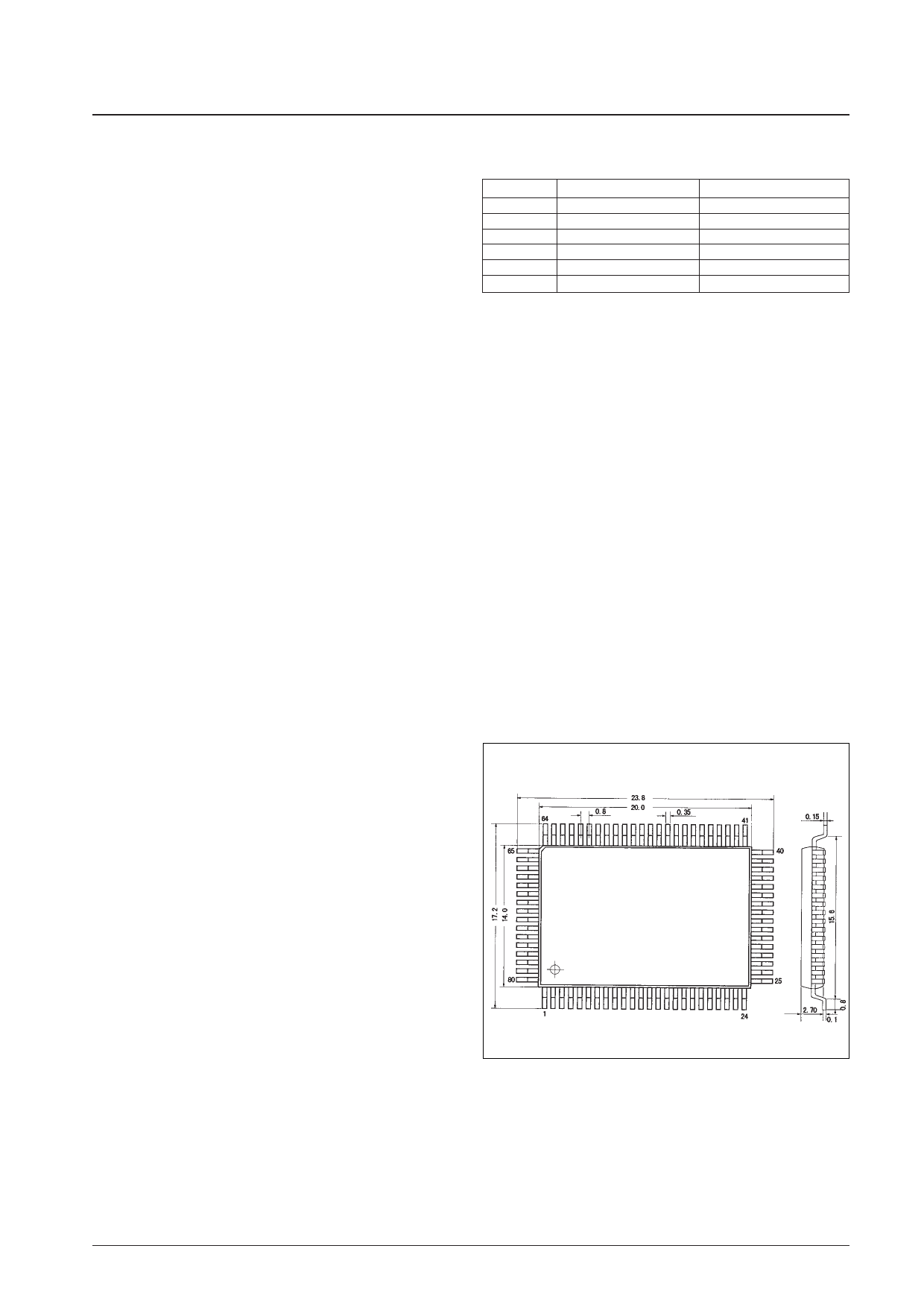
Package Dimensions
unit: mm
3174-QFP80E
[LC5824, 5823, 5822]
SANYO: QIP80E
No. 5944-2/24
Share Link: 