SG1842(2000) データシートの表示(PDF) - Microsemi Corporation
部品番号
コンポーネント説明
メーカー
SG1842 Datasheet PDF : 14 Pages
| |||
PRODUCT DATABOOK 1996/1997
SG1842/SG1843 Series
CURRENT-MODE PWM CONTROLLER
PRODUCTION DATA SHEET
T Y P I C A L A P P L I C A T I O N C I R C U I T S (continued)
VCC
VIN
7 (12)
8 (14)
4 (7)
7 (11)
Q1
2 (3)
SG1842/43
6 (10)
I
1 (1)
R2
MPSA63
C
R1
5 (9)
5 (8)
3 (5)
VCS
RS
I
= VCS Where: V
= 1.67
R1
and V
= 1V (Typ.)
PK R
S
CS
R1+R2
C.S.MAX
tSOFTSTART = -ln
1
-
V - 1.3
EAO
5
R1
R1+R2
R1 R2
R1+R2
C
where; VEAO ≡ voltage at the Error Amp Output under
minimum line and maximum load conditions.
FIGURE 19. — ADJUSTABLE BUFFERED REDUCTION OF CLAMP LEVEL
WITH SOFTSTART
Softstart and adjustable peak current can be done with the external
circuitry shown above.
RA
6
RB
8
4
555
TIMER
2
1
f=
1.44
(RA + 2RB)C
f
=
RB
RA + 2RB
8 (14)
SG1842/43
3
4 (7)
To other
SGX842/43
5 (9)
FIGURE 20. — EXTERNAL DUTY CYCLE CLAMP AND
MULTI-UNIT SYNCHRONIZATION
Precision duty cycle limiting as well as synchronizing several 1842/
1843's is possible with the above circuitry.
2.8V
1.1V
SG1842/43
5V
8 (14)
RT
4 (7)
CT
Discharge
Current
Id = 8.2mA
2.5V
SG1842/43
2 (3)
Ri
1 (1)
RF
RF ³ 10K
0.5mA
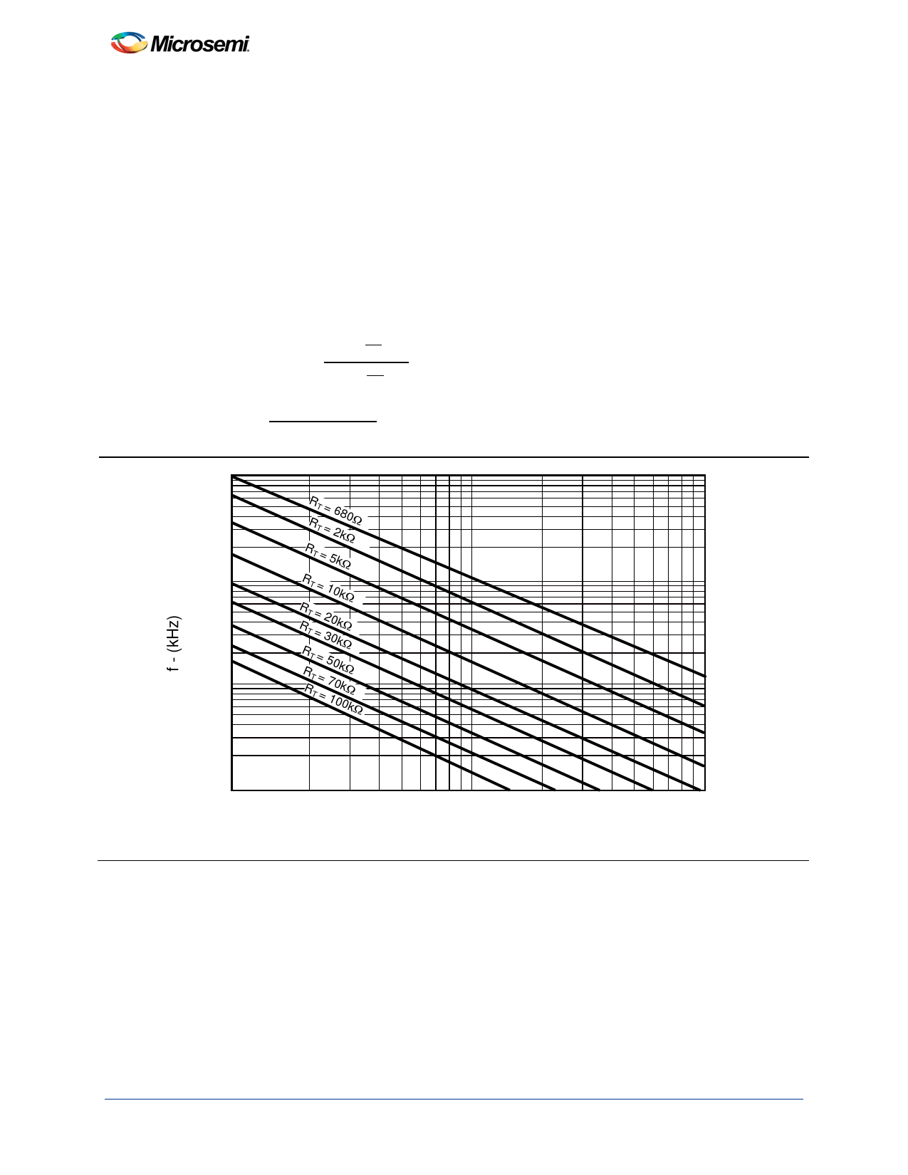
FIGURE 21. — OSCILLATOR CONNECTION
The oscillator is programmed by the values selected for the timing
components RT and CT. Refer to application information for
calculation of the component values.
FIGURE 22. — ERROR AMPLIFIER CONNECTION
Error amplifier is capable of sourcing and sinking current up to 0.5mA.
12
Copyright © 2000
Rev. 1.6 4/00
Share Link: 