ADR01(RevF) データシートの表示(PDF) - Analog Devices
部品番号
コンポーネント説明
メーカー
ADR01 Datasheet PDF : 20 Pages
| |||
ADR01/ADR02/ADR03/ADR06
APPLICATIONS
The ADR01/ADR02/ADR03/ADR06 are high precision, low
drift 10 V, 5 V, 2.5 V, and 3.0 V voltage references available in an
ultracompact footprint. The SOIC-8 version of the devices is a
drop-in replacement of the REF01/REF02/ REF03 sockets with
improved cost and performance.
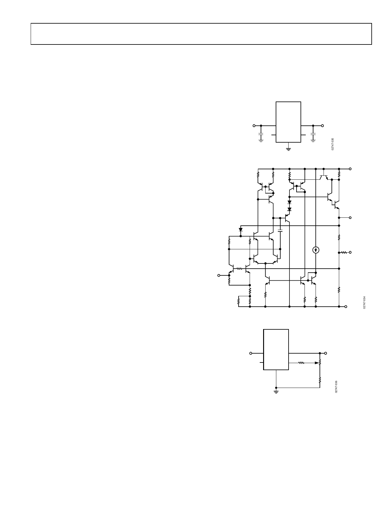
These devices are standard band gap references. The band gap
cell contains two NPN transistors (Q18 and Q19) that differ in
emitter area by 2×. The difference in their VBE produces a
proportional-to-absolute temperature current (PTAT) in R14,
and, when combined with the VBE of Q19, produces a band gap
voltage, VBG, that is almost constant in temperature. With an
internal op amp and the feedback network of R5 and R6, VO is set
precisely at 10 V, 5 V, 2.5 V, and 3.0 V for the ADR01, ADR02,
ADR06, and ADR03, respectively. Precision laser trimming of
the resistors and other proprietary circuit techniques are used to
further enhance the initial accuracy, temperature curvature, and
drift performance of the ADR01/ADR02/ADR03/ADR06.
R1
R2
R3
VIN
R4
Q23
Q1
Q2 Q7
Q8
Q3
D1
D2
Q4
D3
C1
Q13
Q12
R12
R13
Q14 Q15
Q9
Q10
VO
R5
I1
2X
Q18
R27
TEMP R14
1X
Q19
Q16
R32
R24
R17 R11
VBG R20
TRIM
Q17
Q20
R6
R41
R42
GND
Figure 34. Simplified Schematic Diagram
The PTAT voltage is made available at the TEMP pin of the
ADR01/ADR02/ADR03/ADR06. It has a stable 1.96 mV/°C
temperature coefficient, such that users can estimate the
temperature change of the device by knowing the voltage
change at the TEMP pin.
APPLYING THE ADR01/ADR02/ADR03/ADR06
The devices can be used without any external components to
achieve the specified performance. Because of the internal op
amp amplifying the band gap cell to 10 V/5 V/2.5 V/3.0 V,
power supply decoupling helps the transient response of the
ADR01/ADR02/ADR03/ADR06. As a result, a 0.1 µF ceramic
type decoupling capacitor should be applied as close as possible
to the input and output pins of the device. An optional 1 µF to
10 µF bypass capacitor can also be applied at the VIN node to
maintain the input under transient disturbance.
VIN
C1
0.1µF
U1
ADR01/
ADR02/
ADR03/
ADR06
VIN VOUT
TEMP TRIM
GND
VO
C2
0.1µF
Figure 35. Basic Configuration
Output Adjustment
The ADR01/ADR02/ADR03/ADR06 trim terminal can be used
to adjust the output voltage over a nominal voltage. This feature
allows a system designer to trim system errors by setting the
reference to a voltage other than 10 V/5 V/2.5 V/3.0 V. For finer
adjustment, a series resistor of 470 kΩ can be added. With the
configuration shown in Figure 36, the ADR01 can be adjusted
from 9.70 V to 10.05 V, the ADR02 can be adjusted from 4.95 V
to 5.02 V, the ADR06 can be adjusted from 2.8 V to 3.3 V, and
the ADR03 can be adjusted from 2.3 V to 2.8 V. Adjustment of
the output does not significantly affect the temperature per-
formance of the device, provided the temperature coefficients of
the resistors are relatively low.
U1
ADR01/
ADR02/
ADR03/
ADR06
VIN
VIN VOUT
VO
TEMP TRIM
GND
R1
470kΩ
pot
10kΩ
R2
1kΩ
Figure 36. Optional Trim Adjustment
Temperature Monitoring
As described previously, the ADR01/ADR02/ADR03/ADR06
provide a TEMP output (Pin 3) that varies linearly with tem-
perature. This output can be used to monitor the temperature
change in the system. The voltage at VTEMP is approximately
550 mV at 25°C, and the temperature coefficient is approximately
1.96 mV/°C (see Figure 37). A voltage change of 39.2 mV at the
TEMP pin corresponds to a 20°C change in temperature.
Rev. F | Page 15 of 20
Share Link: 