MF832M1-GMCAVXX データシートの表示(PDF) - MITSUBISHI ELECTRIC
部品番号
コンポーネント説明
メーカー
MF832M1-GMCAVXX Datasheet PDF : 22 Pages
| |||
MITSUBISHI MEMORY CARD
FLASH MEMORY CARDS
COMMAND DEFINITION
The corresponding memories of the card are set to
read/write mode and the operation is
controlled by the software command written in the
control register.
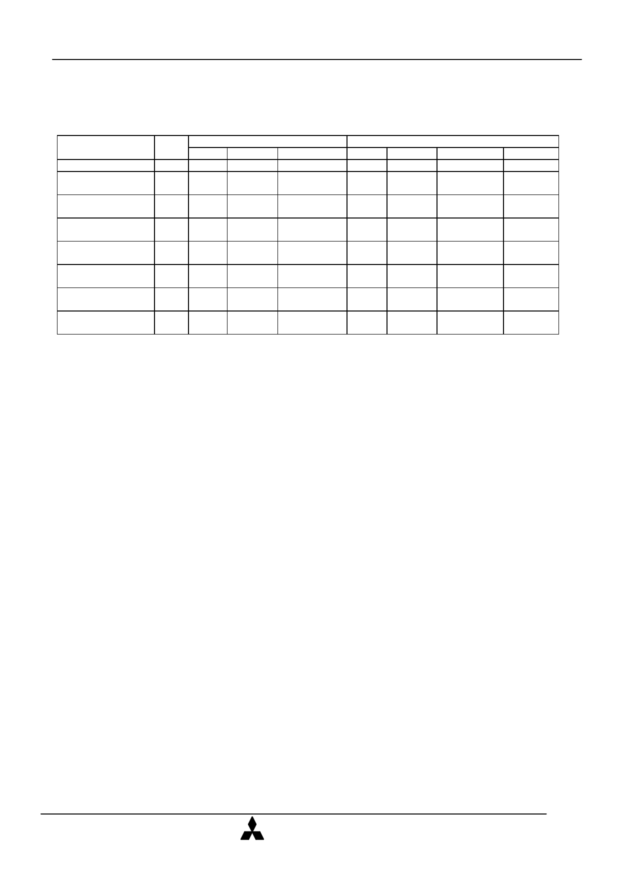
COMMAND DEFINITION TABLE
Command
Read/Reset
Programme setup/
Programme
Erase Setup/
Erase Confirm
Programme
Suspend/Resume
Erase Suspend/
Resume
Read Status
Register
Clear Status
Register
Read Device
Identifier Code
Bus
cycles
1
2
2
2
2
2
1
2
Mode
Write
Write
Write
Write
Write
Write
Write
Write
First bus cycle
Address Data in
ZA FFh(FFFFh)
PA
40(4040)h
BA
20(2020)h
PA B0(B0B0)h
BA B0(B0B0)h
ZA
70(7070)h
ZA
50(5050)h
ZA
90(9090)h
Mode
-
Write
Second bus cycle
Address Data in
-
-
PA
PD
Write
BA D0(D0D0)h
Write
PA D0(D0D0)h
Write
BA D0(D0D0)h
Read
ZA
-
-
-
-
Read DIA
-
Data out
-
-
-
-
-
RD
-
DID
Note 3: Indicates the basic functions of commands and should not write another commands.
Refer to the algorithms to operate.
Signal status is defined in function table and bus status.
Parenthesized data shows the data for 16 bit mode operation.
ZA=an address of a memory zone (Please refer to the memory zone)
PA=Programming address
PD=Programming data
BA=An address of a memory block (Please refer to the memory block)
RD=Data of status Register
DIA=Device identifier address
000000h for manufacturer code 000002h for device code
DID=Device identifier data
2MB=manufacturer code : 89 (8989)h device code : A6h (A6A6)h
Others=manufacturer code : 89 (8989)h device code : AA (AAAA)h
Read/Reset
The memory in the card is switched to read mode by
writing FFh (FFFFh for 16 bit operation) into
the control resister. This mode is maintained
until the contents of register are changed. This
mode needs to be written to every
memory zone to which access is required.
Programme Setup/Programme
The setup programme command sets up the card for
programming. It is applied when 40h (4040h for 16
bit operation) is written to control register.
Programming will take place automatically after
latching the address and data which are applied at
the rising edge of WE#.
The completion of programme can be confirmed by
reading status register.
(For details please refer to the algorithm)
Erase Setup/Erase confirm
The erase setup is a command to set up the memory
block for erasure. Writing setup erase command 20h
(2020h for 16 bit operation) in the control register
followed by erase confirm command D0h (D0D0h
for 16 bit operation) will initiate a erasure
operation. Erasing will take place automatically
after the rising edge of WE# controlled by a internal
timer. The completion of
erase can be confirmed by reading status register.
(For details please refer to the algorithm)
These commands will not erase all the data of a
memory card and should be repeated for all the
required memory blocks. At an eight bit access
mode it should be noticed that the erasure of a
memory block will result in odd byte or even byte
erasure.
MITSUBISHI
ELECTRIC
5/22
Feb.1999 Rev2.0
Share Link: 