AAT3697 データシートの表示(PDF) - Advanced Analogic Technologies
部品番号
コンポーネント説明
メーカー
AAT3697 Datasheet PDF : 19 Pages
| |||
BatteryManagerTM
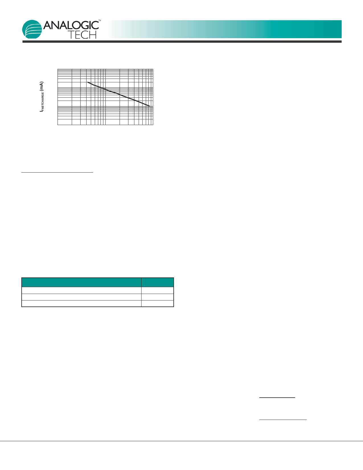
10000
1000
100
10
1
10
100
RSET (kΩ)
Figure 2: ICH vs. RSET.
Protection Circuitry
Programmable Watchdog Timer
The AAT3697 contains a watchdog timing circuit to shut
down charging functions in the event of a defective bat-
tery cell not accepting a charge over a preset period of
time. Typically, a 0.1µF ceramic capacitor is connected
between the CT pin and ground. When a 0.1µF ceramic
capacitor is used, the device will time out a shutdown
condition if the trickle charge mode exceeds 25 minutes
and a combined trickle charge plus fast charge mode of
3 hours. When the device transitions to the constant
voltage mode, the timing counter is reset and will time
out after an additional 3 hours if the charge current does
not drop to the charge termination level.
Mode
Trickle Charge (TC) Time Out
Trickle Charge (TC) + Fast Charge (CC) Time Out
Constant Voltage (VC) Mode Time Out
Time
25 minutes
3 hours
3 hours
Table 2: Summary for a 0.1µF Ceramic Capacitor
Used for the Timing Capacitor.
The CT pin is driven by a constant current source and will
provide a linear response to increases in the timing
capacitor value. Thus, if the timing capacitor were to be
doubled from the nominal 0.1µF value, the time-out
periods would be doubled.
If the programmable watchdog timer function is not
needed, it can be disabled by terminating the CT pin to
ground. The CT pin should not be left floating or un-
terminated, as this will cause errors in the internal tim-
ing control circuit.
The constant current provided to charge the timing
capacitor is very small, and this pin is susceptible to
PRODUCT DATASHEET
AAT3697
2A Lithium-Ion/Polymer Battery Charger
noise and changes in capacitance value. Therefore, the
timing capacitor should be physically located on the
printed circuit board layout as close as possible to the CT
pin. Since the accuracy of the internal timer is domi-
nated by the capacitance value, a 10% tolerance or bet-
ter ceramic capacitor is recommended. Ceramic capaci-
tor materials, such as X7R and X5R types, are a good
choice for this application.
Over-Voltage Protection
An over-voltage event is defined as a condition where the
voltage on the BAT pin exceeds the maximum battery
charge voltage and is set by the over-voltage protection
threshold (VOVP). If an over-voltage condition occurs, the
AAT3697 charge control will shut down the device until the
voltage on the BAT pin drops below VOVP. The AAT3697 will
resume normal charging operation after the over-voltage
condition is removed. During an over-voltage event, the
STAT LEDs will report a system fault, and the actual fault
condition can be read via the DATA pin signal.
Over-Temperature Shutdown
The AAT3697 has a thermal protection control circuit
which will shut down charging functions should the inter-
nal die temperature exceed the preset thermal limit
threshold.
Battery Temperature Fault Monitoring
In the event of a battery over-temperature condition, the
charge control will turn off the internal pass device and
report a battery temperature fault on the DATA pin func-
tion. The STAT LEDs will also display a system fault. After
the system recovers from a temperature fault, the device
will resume charging operation.
The AAT3697 checks battery temperature before starting
the charge cycle, as well as during all stages of charging.
This is accomplished by monitoring the voltage at the TS
pin. Either a negative temperature coefficient thermistor
(NTC) or positive temperature coefficient thermistor
(PTC) can be used because the AAT3697 checks to see
that the voltage at TS is within a voltage window bound-
ed by VTS1 and VTS2. Please see the equations below for
specifying resistors:
RT1 and RT2 for use with NTC Thermistor
Eq. 2:
RT1 =
5 ⋅ RTH ⋅ RTC
3 ⋅ (RTC - RTH)
RT2 =
5 ⋅ RTH ⋅ RTC
(2 ⋅ RTC) - (7 ⋅ RTH)
12
www.analogictech.com
3697.2008.02.1.3
Share Link: 