SC9256 データシートの表示(PDF) - Silan Microelectronics
部品番号
コンポーネント説明
メーカー
SC9256 Datasheet PDF : 24 Pages
| |||
Silan
Semiconductors
SC9256
Note: 1. Reference frequencies marked with an asterisk “*”can only be generated with a 4.5MHZ crystal oscillator.
2. (*1)Standby mode
Standby mode occurs when bits R0,R1,R2,and R3 are all set to “1”.In standby mode, the programmable
counter stops, and FM, AM and IFIN(when selected IFIN) are set to “amp off” state (pins at “L” level). This
saves current consumption when the radio is turned off. The DO pins become high impedance during
standby mode.
During standby mode, the I/O ports (I/O-5~I/O-6) and output ports (OT1~OT4) can be controlled and the
crystal oscillator can be turned on and off.
3.The system is set to standby mode when power is turned on. At this time, the crystal oscillator is not
oscillating and the I/O ports are set to input mode.
Programmable counter
The programmable counter section consists of a 1/2 prescaler, a 2 modulus prescaler and a 4bit +12bit
programmable binary counter.
1. Setting programmable counter
16 bits of divisor data and 2 bits, which indicate the dividing mode, are set in the programmable counter.
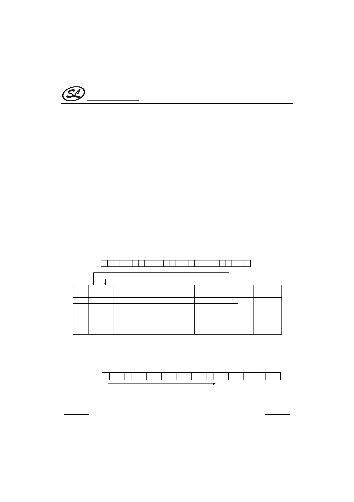
(1) Setting dividing mode
The FM and MODE bits are used to select the input pin and the dividing mode (pulses wallow mode or
direct dividing mode). There are 4 possible choices, shown in the table below .Select one based on the
frequency band used.
LSB
Address D0H
FM MODE
MSB
MODE FM MODE DIVIDING MODE
LF 0
HF 0
FML 1
0 Direct dividing mode
1
Pulse swallow mode
0
FMH 1
1
1/2 + pulse swallow
mode
TYPICAL
INPUT FREQUENCY
RECEIVING BAND
RANGE
LW,MW,SWL
0.5 ~ 20MHz
SWH
1 ~ 40MHz
30 ~ 130MHz
FM
30 ~ 150MHz
FM
30 ~ 130MHz
INPUT
PIN
FREQUENCY
AMIN
n
FMIN
2n
(2) Setting divisor
The divisor for the programmable counter is set as binary data in bits P0~P15.
• Pulse swallow mode (16 bits)
Address D0H
LSB
P0 P1 P2 P3 P4 P5 P6 P7 P8 P9 P10 P11 P12 P13 P14 P15
20
215
MSB
Divisor setting range (pulse swallow mode):n=210H~FFFH (528~65535)
(Note) With the 1/2+pulse swallow mode, the actual divisor is twice the programmed value.
HANGZHOU SILAN MICROELECTRONICS JOINT-STOCK CO.,LTD
REV: 1.0
10
2002.01.30.
Share Link: 