NTE3049 データシートの表示(PDF) - NTE Electronics
部品番号
コンポーネント説明
メーカー
NTE3049 Datasheet PDF : 2 Pages
| |||
Electrical Characteristics: (TA = +25°C unless otherwise specified)
Parameter
Symbol
Test Conditions
Min Typ Max Unit
Input LED
Reverse Leakage Current IR VR = 6V
Forward Voltage
VF IF = 30mA
Output Detector (IF = 0 unless otherwise specified)
Leakage With LED OFF IDRM1 Either Direction, VDRM = 400V, Note 2
Peak On–State Voltage VTM Either Direction, ITM = 100mA Peak
Critical Rate of Rise of
Off–State Voltage
dv/dt Note 4
– 0.05 10
– 1.3 1.5
– 2 100
– 1.8 3.0
1000 2000 –
µA
V
nA
V
V/µs
Coupled
LED Trigger Current,
Current Required to
Latch Output
IFT Main Terminal Voltage = 3V, Note 3
– – 15 mA
Holding Current
Isolation Voltage
Zero Crossing
IH Either Direction
VISO f = 60Hz, t = 1sec
– 100
7500 –
–
µA
– VAC(pk)
Inhibit Voltage
VIH IF = 15mA, MT1–MT2 Voltage Above
–
5 20
V
Which Device Will Not Trigger
Leakage in Inhibit State IDRM2 IF = 15mA, VDRM = 400V, Off–State
–
– 500 µA
Note 2. Test voltage must be applied within dv/dt rating.
Note 3. This device is guaranteed to trigger at an IF1 value less than or equal to max. IFT. Therefore,
recommended operating IF lies between max. IFT (15mA) and absolute max. IF (60mA).
Note 4. This is static dv/dt. Commutating dv/dt is a function of the load–driving thyristor only.
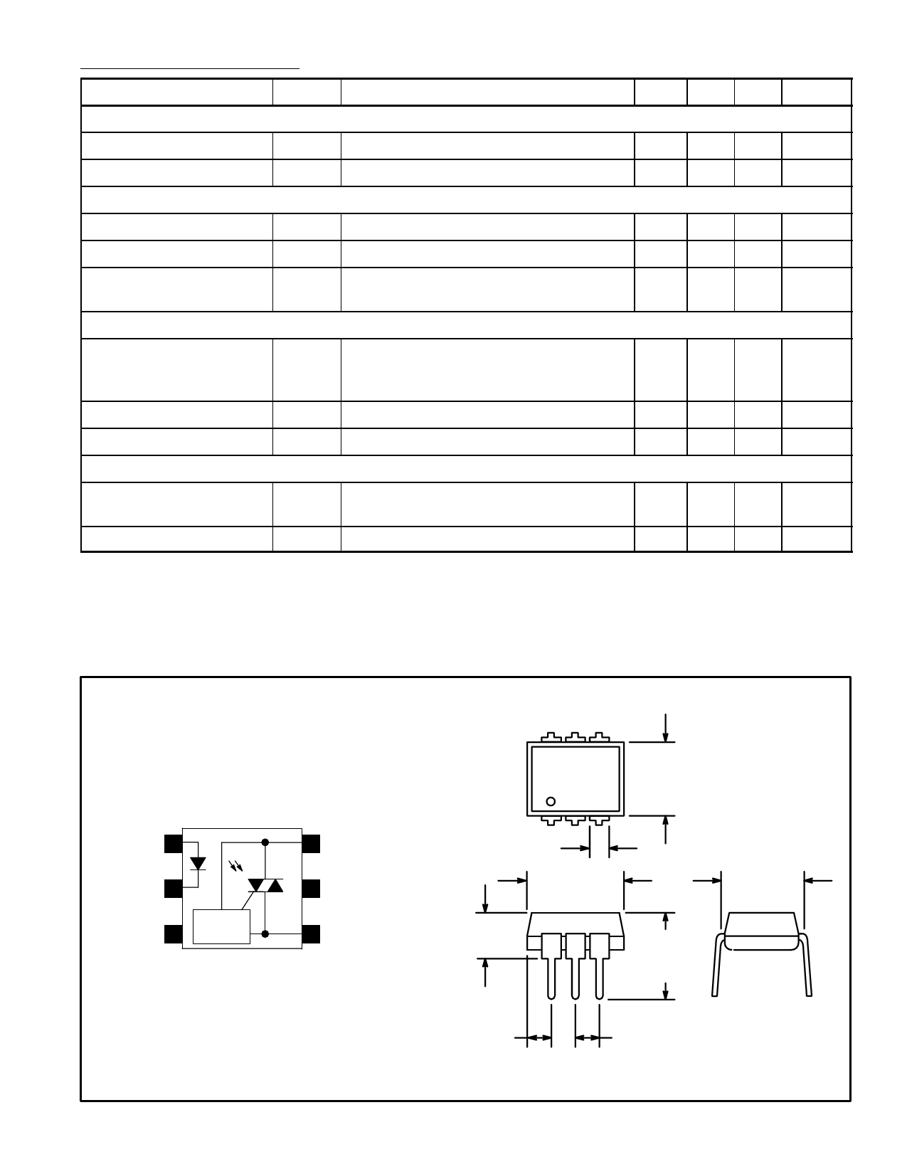
Pin Connection Diagram
6 54
1 23
Anode 1
Cathode 2
N.C. 3
ZERO
CROSSING
CIRCUIT
6 Main Terminal
5
Substrate
Do Not Connect
.070 (1.78)
Max
.350 (8.89)
Max
4 Main Terminal
.200 (5.08)
Max
.260
(6.6)
Max
.350
(8.89)
Max
.300 (7.62)
.085 (2.16)
Max
.100 (2.54)
Share Link: 