MAX700 データシートの表示(PDF) - Maxim Integrated
部品番号
コンポーネント説明
メーカー
MAX700 Datasheet PDF : 6 Pages
| |||
MAX700/MAX701/MAX702
Power-Supply Monitor with Reset
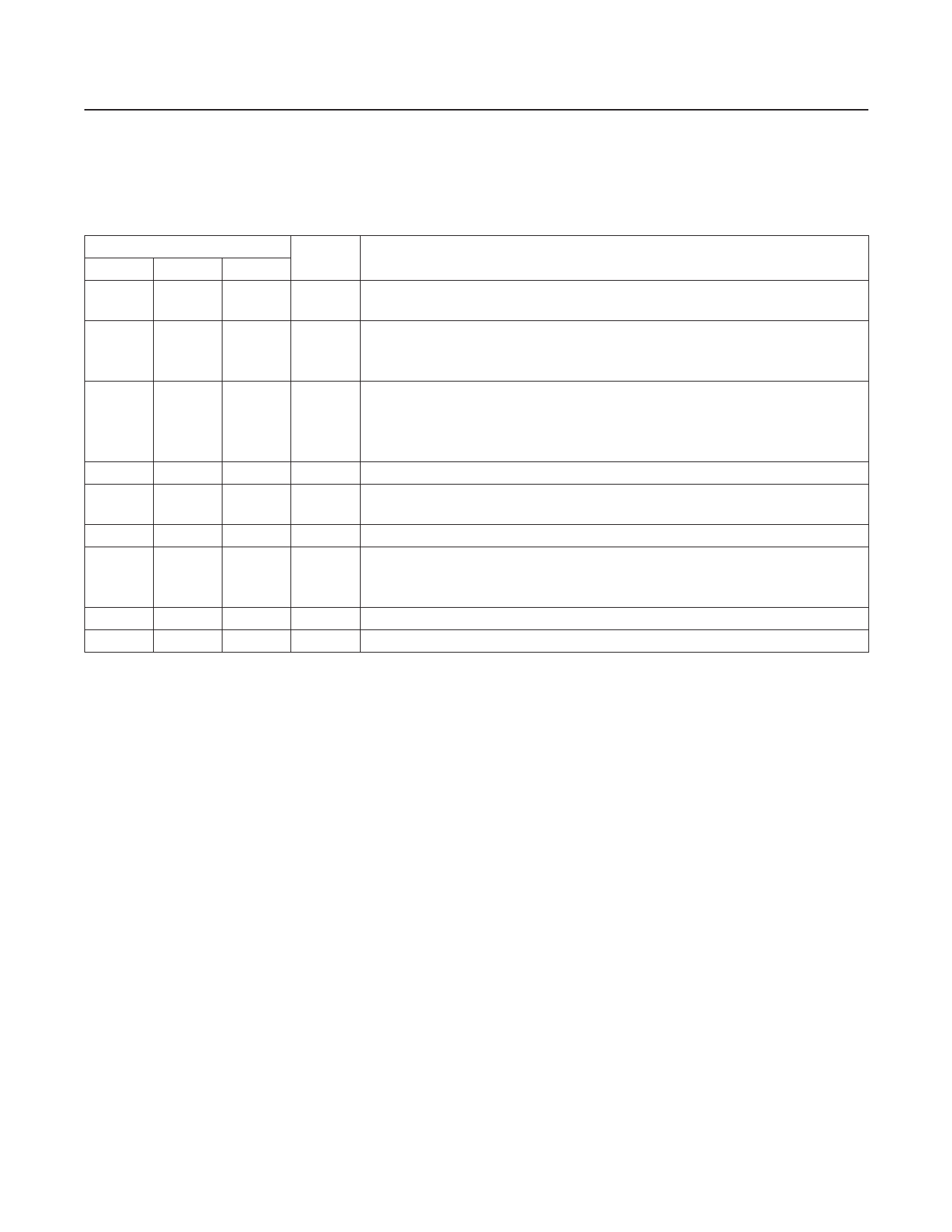
Pin Description
PIN
MAX700 MAX701 MAX702
1
1
1
2
—
—
NAME
FUNCTION
MR
Input for Manual Pushbutton Reset. Has internal 5µA pullup. Low input activates the
RESET/RESET outputs.
The voltage-sense input when CTL = VCC. Its threshold is 1.29V. SENSE always
SENSE remains connected to the internal comparator. So, when VCC is being monitored
internally (CTL = GND), SENSE should be left open circuit.
Normally NOT used when voltage is monitored through VCC (CTL = GND). When
3
—
—
HYST
monitoring through SENSE (CTL = VCC), HYST allows hysteresis to be added,
reducing noise and spurious reset activity (Figure 3). HYST turns on 5µs before the
RESET/RESET outputs are activated, and its on-resistance to GND is typically 1kΩ.
4
4
3
GND Ground
5
6
7
RESET
Goes low when VCC falls below 4.65V, or when CTL = VCC on the MAX700 goes low
when SENSE falls below 1.29V.
6
5
—
RESET Inverted Version of RESET
When CTL = GND, VCC is monitored by the reset circuit. When CTL = VCC, VCC
7
—
—
CTL is ignored and SENSE is monitored, allowing the threshold to be set with external
resistors.
8
8
2
VCC Chip Power and +5V Sensing Input (When CTL = GND on MAX700)
—
2, 3, 7 4, 5, 6, 8 N.C. No Connection
www.maximintegrated.com
Maxim Integrated │ 4
Share Link: 