8254 データシートの表示(PDF) - Intel
部品番号
コンポーネント説明
メーカー
8254 Datasheet PDF : 21 Pages
| |||
8254
The selected Counter’s output latch (OL) latches the
count at the time the Counter Latch Command is
received This count is held in the latch until it is read
by the CPU (or until the Counter is reprogrammed)
The count is then unlatched automatically and the
OL returns to ‘‘following’’ the counting element (CE)
This allows reading the contents of the Counters
‘‘on the fly’’ without affecting counting in progress
Multiple Counter Latch Commands may be used to
latch more than one Counter Each latched Coun-
ter’s OL holds its count until it is read Counter Latch
Commands do not affect the programmed Mode of
the Counter in any way
If a Counter is latched and then some time later
latched again before the count is read the second
Counter Latch Command is ignored The count read
will be the count at the time the first Counter Latch
Command was issued
With either method the count must be read accord-
ing to the programmed format specifically if the
Counter is programmed for two byte counts two
bytes must be read The two bytes do not have to be
read one right after the other read or write or pro-
gramming operations of other Counters may be in-
serted between them
Another feature of the 8254 is that reads and writes
of the same Counter may be interleaved for exam-
ple if the Counter is programmed for two byte
counts the following sequence is valid
1) Read least significant byte
2) Write new least significant byte
3) Read most significant byte
4) Write new most significant byte
If a Counter is programmed to read write two-byte
counts the following precaution applies A program
must not transfer control between reading the first
and second byte to another routine which also reads
from that same Counter Otherwise an incorrect
count will be read
READ-BACK COMMAND
The third method uses the Read-Back Command
This command allows the user to check the count
value programmed Mode and current states of the
OUT pin and Null Count flag of the selected coun-
ter(s)
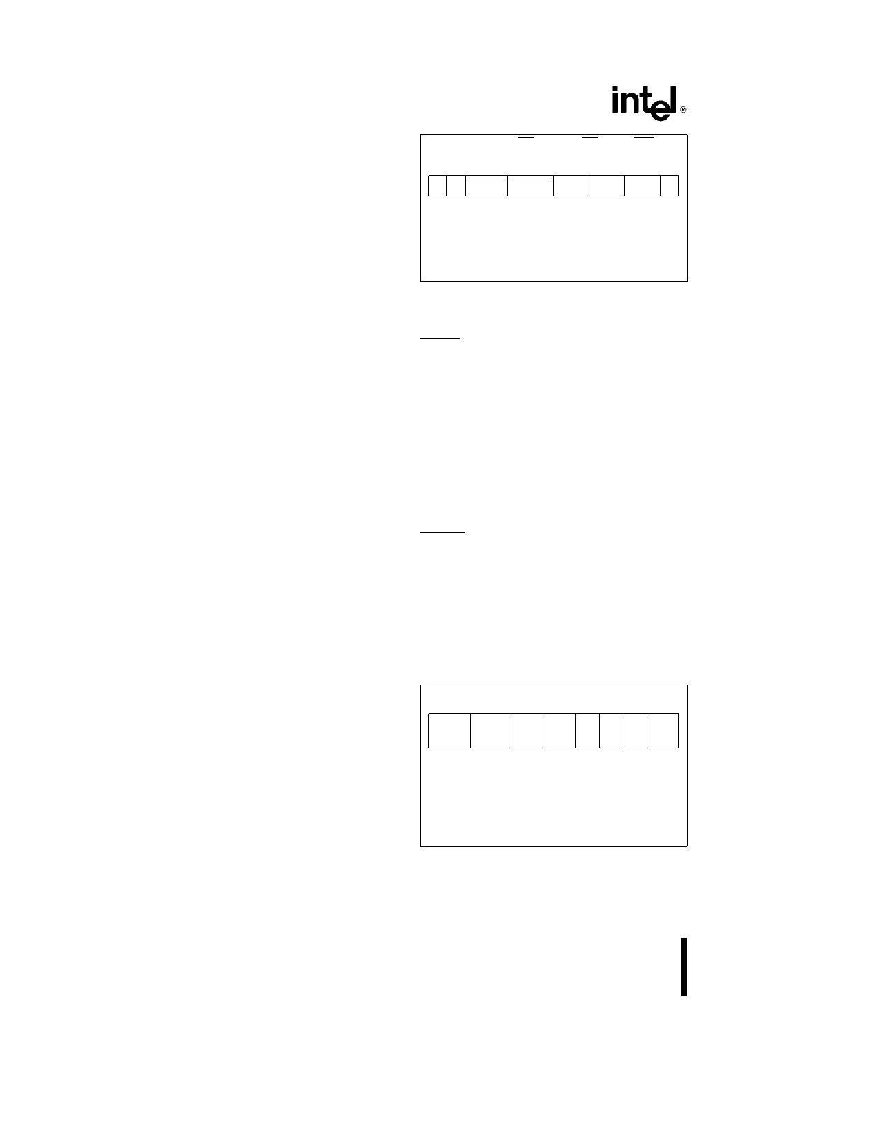
The command is written into the Control Word Reg-
ister and has the format shown in Figure 10 The
command applies to the counters selected by set-
ting their corresponding bits D3 D2 D1 e 1
A0 A1 e 11 CS e 0 RD e 1 WR e 0
D7 D6 D5
D4
D3
D2
D1 D0
1 1 COUNT STATUS CNT 2 CNT 1 CNT 0 0
D5 0 e Latch count of selected counter(s)
D4 0 e Latch status of selected counters(s)
D3 1 e Select Counter 2
D2 1 e Select Counter 1
D1 1 e Select Counter 0
D0 Reserved for future expansion Must be 0
Figure 10 Read-Back Command Format
The read-back command may be used to latch multi-
ple counter output latches (OL) by setting the
COUNT bit D5 e 0 and selecting the desired coun-
ter(s) This single command is functionally equiva-
lent to several counter latch commands one for
each counter latched Each counter’s latched count
is held until it is read (or the counter is repro-
grammed) The counter is automatically unlatched
when read but other counters remain latched until
they are read If multiple count read-back commands
are issued to the same counter without reading the
count all but the first are ignored i e the count
which will be read is the count at the time the first
read-back command was issued
The read-back command may also be used to latch
status information of selected counter(s) by setting
STATUS bit D4 e 0 Status must be latched to be
read status of a counter is accessed by a read from
that counter
The counter status format is shown in Figure 11 Bits
D5 through D0 contain the counter’s programmed
Mode exactly as written in the last Mode Control
Word OUTPUT bit D7 contains the current state of
the OUT pin This allows the user to monitor the
counter’s output via software possibly eliminating
some hardware from a system
D7
D6 D5 D4 D3 D2 D1 D0
Output
Null
Count
RW1
RW0
M2
M1
M0
BCD
D7 1 e OUT Pin is 1
0 e OUT Pin is 0
D6 1 e Null Count
0 e Count available for reading
D5 – D0 Counter programmed mode (see Figure
7)
Figure 11 Status Byte
8
Share Link: 