TL431CDR2 データシートの表示(PDF) - ON Semiconductor
部品番号
コンポーネント説明
メーカー
TL431CDR2 Datasheet PDF : 19 Pages
| |||
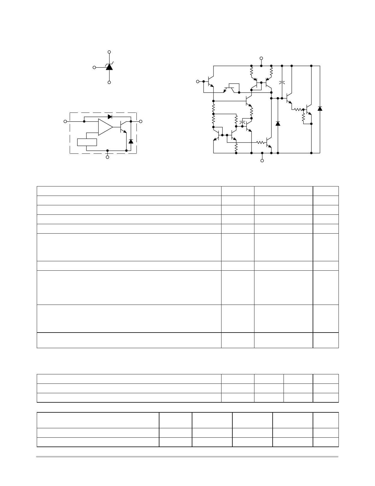
TL431, A, B Series, NCV431A, B
Symbol
Reference
(R)
Cathode
(K)
Anode
(A)
Reference
(R)
Representative Schematic Diagram
Component values are nominal
Cathode (K)
800
800
20 pF
Representative Block Diagram
Reference
(R)
+
Cathode
(K)
3.28 k
150
4.0 k
20 pF
2.4 k
7.2 k
10 k
−
2.5 Vref
1.0 k
800
Anode (A)
This device contains 12 active transistors.
Anode (A)
MAXIMUM RATINGS (Full operating ambient temperature range applies, unless otherwise noted.)
Rating
Symbol
Value
Unit
Cathode to Anode Voltage
VKA
37
V
Cathode Current Range, Continuous
IK
−100 to +150
mA
Reference Input Current Range, Continuous
Iref
−0.05 to +10
mA
Operating Junction Temperature
TJ
150
°C
Operating Ambient Temperature Range
TL431I, TL431AI, TL431BI
TL431C, TL431AC, TL431BC
NCV431AI, NCV431B, TL431BV
TA
°C
−40 to +85
0 to +70
−40 to +125
Storage Temperature Range
Total Power Dissipation @ TA = 25°C
Derate above 25°C Ambient Temperature
D, LP Suffix Plastic Package
P Suffix Plastic Package
DM Suffix Plastic Package
Tstg
−65 to +150
°C
PD
W
0.70
1.10
0.52
Total Power Dissipation @ TC = 25°C
Derate above 25°C Case Temperature
D, LP Suffix Plastic Package
P Suffix Plastic Package
PD
W
1.5
3.0
ESD Rating
HBM
>2000
V
MM
>200
Stresses exceeding Maximum Ratings may damage the device. Maximum Ratings are stress ratings only. Functional operation above the
Recommended Operating Conditions is not implied. Extended exposure to stresses above the Recommended Operating Conditions may affect
device reliability.
RECOMMENDED OPERATING CONDITIONS
Condition
Symbol
Min
Max
Unit
Cathode to Anode Voltage
Cathode Current
THERMAL CHARACTERISTICS
VKA
Vref
36
V
IK
1.0
100
mA
Characteristic
Symbol
D, LP Suffix
Package
P Suffix
Package
DM Suffix
Package
Unit
Thermal Resistance, Junction−to−Ambient
Thermal Resistance, Junction−to−Case
RqJA
178
114
240
°C/W
RqJC
83
41
−
°C/W
http://onsemi.com
2
Share Link: 