MAX4521CSE(2001) データシートの表示(PDF) - Maxim Integrated
部品番号
コンポーネント説明
メーカー
MAX4521CSE Datasheet PDF : 14 Pages
| |||
19-1136; Rev 3; 10/01
Quad, Low-Voltage, SPST Analog Switches
General Description
The MAX4521/MAX4522/MAX4523 are quad, low-volt-
age, single-pole/single-throw (SPST) analog switches.
On-resistance (100Ω max) is matched between switch-
es to 4Ω max, and is flat (12Ω max) over the specified
signal range. Each switch can handle Rail-to-Rail® ana-
log signals. The off-leakage current is only 1nA at
+25°C and 10nA at +85°C.
The MAX4521 has four normally closed (NC) switches,
and the MAX4522 has four normally open (NO) switch-
es. The MAX4523 has two NC switches and two NO
switches.
These CMOS switches can operate with dual power
supplies ranging from ±2V to ±6V or a single supply
between +2V and +12V. They are fully specified for sin-
gle +2.7V operation.
All digital inputs have +0.8V and +2.4V logic thresh-
olds, ensuring TTL/CMOS-logic compatibility when
using ±5V or a single +5V supply.
Applications
Battery-Operated Equipment
Data Acquisition
Test Equipment
Avionics
Audio Signal Routing
Networking
Features
o +2V to +12V Single Supply
±2V to ±6V Dual Supplies
o 100Ω Signal Paths with ±5V Supplies
o Low Power Consumption, <1µW
o 4 Separately Controlled SPST Switches
o Rail-to-Rail Signal Handling
o Pin Compatible with Industry-Standard
DG211/DG212/DG213
o >2kV ESD Protection per Method 3015.7
o TTL/CMOS-Compatible Inputs with ±5V or
Single +5V Supply
Ordering Information
PART
TEMP. RANGE PIN-PACKAGE
MAX4521CPE
0°C to +70°C
16 Plastic DIP
MAX4521CSE
0°C to +70°C
16 Narrow SO
MAX4521CEE
0°C to +70°C
16 QSOP
MAX4521CUE
0°C to +70°C
16 TSSOP
MAX4521CGE
0°C to +70°C
16 QFN
MAX4521C/D
0°C to +70°C
Dice*
Ordering Information continued at end of data sheet.
*Contact factory for dice specifications.
Rail-to-Rail is a registered trademark of Nippon Motorola, Ltd.
Pin Configurations continued at end of data sheet.
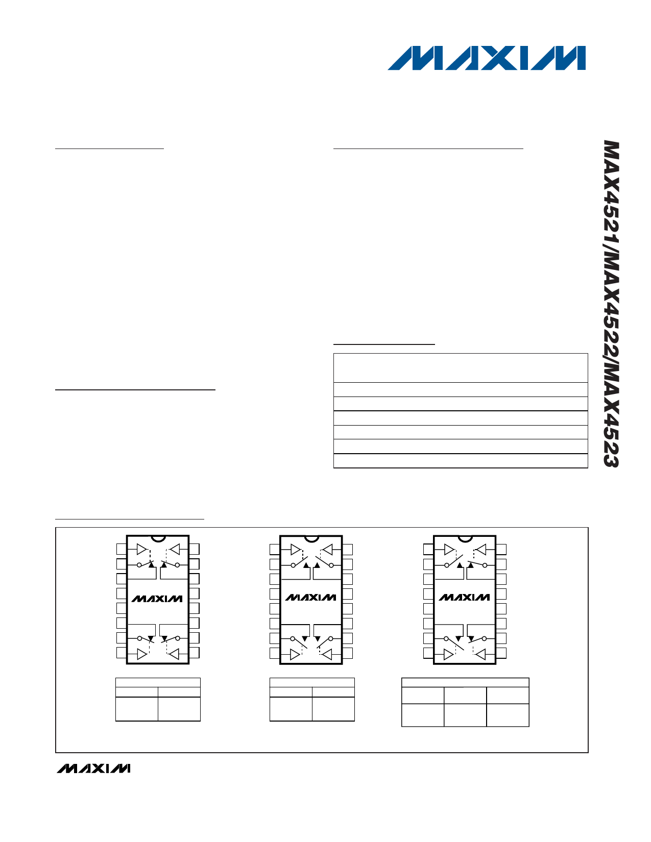
Pin Configurations/Functional Diagrams/Truth Tables
TOP VIEW
IN1 1
COM1 2
NC1 3
V- 4
GND 5
NC4 6
COM4 7
IN4 8
MAX4521
16 IN2
15 COM2
14 NC2
13 V+
12 N.C.
11 NC3
10 COM3
9 IN3
DIP/SO/QSOP/TSSOP
MAX4521
LOGIC
SWITCH
0
ON
1
OFF
N.C. = NOT CONNECTED
IN1 1
COM1 2
NO1 3
V- 4
GND 5
NO4 6
COM4 7
MAX4522
16 IN2
15 COM2
14 NO2
13 V+
12 N.C.
11 NO3
10 COM3
IN4 8
9 IN3
DIP/SO/QSOP/TSSOP
MAX4522
LOGIC
SWITCH
0
OFF
1
ON
SWITCHES SHOWN FOR LOGIC "0" INPUT
IN1 1
COM1 2
NO1 3
V- 4
GND 5
NO4 6
COM4 7
IN4 8
MAX4523
16 IN2
15 COM2
14 NC2
13 V+
12 N.C.
11 NC3
10 COM3
9 IN3
DIP/SO/QSOP/TSSOP
LOGIC
MAX4523
SWITCHES
1, 4
SWITCHES
2, 3
0
OFF
ON
1
ON
OFF
________________________________________________________________ Maxim Integrated Products 1
For pricing, delivery, and ordering information, please contact Maxim/Dallas Direct! at
1-888-629-4642, or visit Maxim’s website at www.maxim-ic.com.
Share Link: 