L6565D データシートの表示(PDF) - STMicroelectronics
部品番号
コンポーネント説明
メーカー
L6565D Datasheet PDF : 17 Pages
| |||
L6565
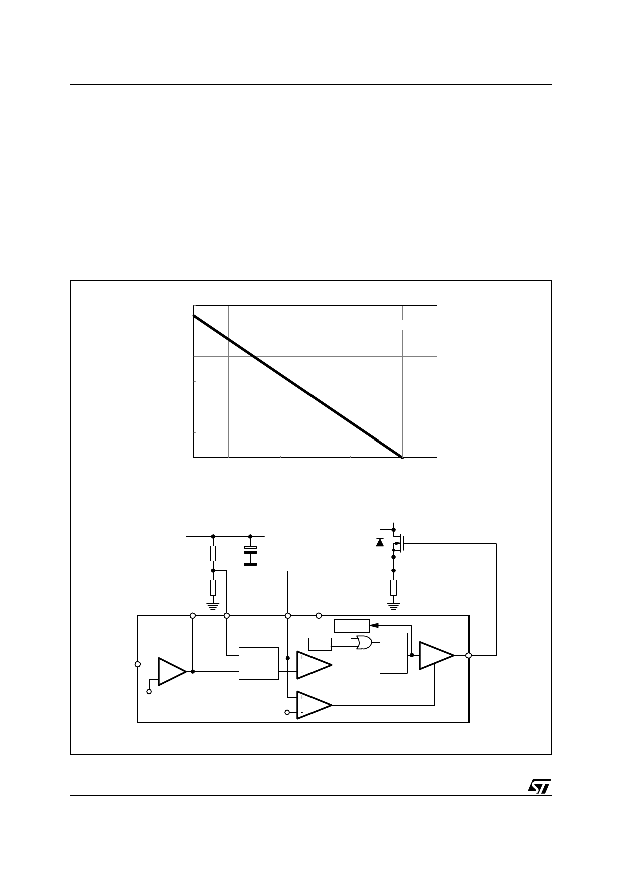
It acts on the clamp level of the control voltage Vcsx, that is on the overcurrent setpoint, so that it is a function
of the converter's input voltage sensed through a dedicated pin (#3, VFF): the higher the input voltage, the lower
the setpoint. This is illustrated in the diagram of figure 17a that shows the relationship between the voltage at
the pin VFF and Vcsx (with the error amplifier saturated high in the attempt of keeping output voltage regulation).
The schematic in figure 17b shows also how the function is included in the control loop. With a proper selection
of the external divider R1-R2 it is possible to achieve the optimum compensation described by the lower curve
in the diagram of figure 16.
In applications where this function is not wanted, e.g. because of a narrow input voltage range, the VFF pin can
be simply grounded, thus saving the resistor divider. The overcurrent setpoint will be then fixed at the maximum
value of about 1.4V (1.5V max.).
Line Feedforward is also beneficial to other characteristics of quasi-resonant converters: it improves their input
ripple rejection ability and limits the variation of the power stage's small-signal gain versus the line voltage.
Figure 17. a) Overcurrent setpoint vs. VFF voltage; b) Line Feedforward function block
Vcsx [V]
1.5
VCOMP = Upper clamp
1
a)
0.5
0
0
0.5
1
1.5
2
2.5
3
3.5
VVFF [V]
+Vin
R1
R2
Rs
COMP
2
INV 1
-
E/A
+
VFF
CS
3
4
VOLTAGE
FEED
FORWARD
ZCD
5
starter STOP
STARTER
ZCD
PWM
S
Q
R
DRIVER
(reset-dominant)
7
GD
2.5V
DISABLE
Hiccup
2V
L6565
b)
10/17
Share Link: 