5962R3829436SNA データシートの表示(PDF) - Aeroflex UTMC
部品番号
コンポーネント説明
メーカー
5962R3829436SNA Datasheet PDF : 15 Pages
| |||
WRITE CYCLE
A combination of W less than V IL(max), E 1less than V IL(max),
and E2 greater than VIH(min) defines a write cycle. The state of
G is a “don’t care” for a write cycle. The outputs are placed in
the high-impedance state when either G is greater than
VIH(min), or when W is less than VIL(max).
Write Cycle 1, the Write Enable-controlled Access shown in
figure 4a, is defined by a write terminated byW going high, with
E1and E2 still active. The write pulse width is defined by t WLWH
when the write is initiated byW, and by tETWH when the write
is initiated by the latter of E1 or E2. Unless the outputs have
been previously placed in the high-impedance state by G, the
user must wait tWLQZ before applying data to the eight
bidirectional pins DQ(7:0) to avoid bus contention.
Write Cycle 2, the Chip Enable-controlled Access shown in
figure 4b, is defined by a write terminated by the latter of E1 or
E2 going inactive. The write pulse width is defined by tWLEF
when the write is initiated by W, and by tETEF when the write
is initiated by the latter of E1 or E2 going active. For the W
initiated write, unless the outputs have been previously placed
in the high-impedance state by G, the user must wait tWLQZ
before applying data to the eight bidirectional pins DQ(7:0) to
avoid bus contention.
RADIATION HARDNESS
The UT67164 SRAM incorporates special design and layout
features which allow operation in high-level radiation
environments.
Table 2. Radiation Hardness
Design Specifications1
Total Dose
1.0E6 rads(Si)
Dose Rate Upset
1.0E9 rads(Si)/s 20ns pulse
Dose Rate Survival 1.0E12 rads(Si)/s 20ns pulse
Single-Event Upset 1.0E-10 errors/bit day2
Neutron Fluencs
3.0E14 n/cm2
Notes:
1. The SRAM will not latchup during radiation exposure under recommended
operating conditions.
2. 90% Adam’s worst case spectrum (-55oC to 125+oC).
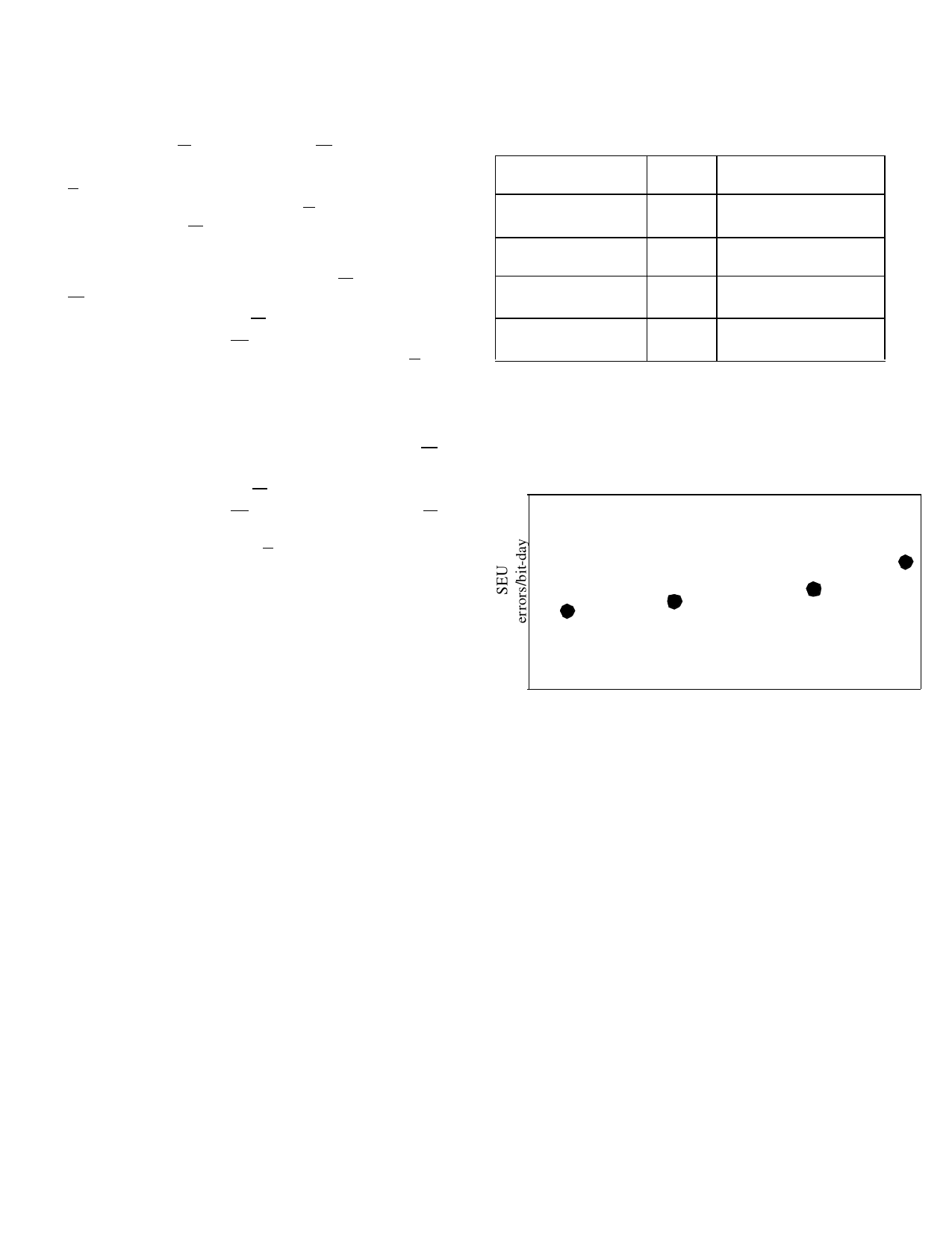
Table 3. SEU versus Temperature
10-4
10-6
10-8
10-10
10-13
10-11
10-12 10-13
10-10
10-14
10-16
-55 -35 -15 5 25 45 65 85 105 125
Temperature (oC)
3
Share Link: 