TS921IYD データシートの表示(PDF) - STMicroelectronics
部品番号
コンポーネント説明
メーカー
TS921IYD Datasheet PDF : 14 Pages
| |||
Macromodels
3 Macromodels
TS921
3.1 Important note concerning this macromodel
Please consider following remarks before using this macromodel:
● All models are a trade-off between accuracy and complexity (i.e. simulation time).
● Macromodels are not a substitute to breadboarding; rather, they confirm the validity of a
design approach and help to select surrounding component values.
● A macromodel emulates the NOMINAL performance of a TYPICAL device within
SPECIFIED OPERATING CONDITIONS (i.e. temperature, supply voltage, etc.). Thus the
macromodel is often not as exhaustive as the datasheet, its goal is to illustrate the main
parameters of the product.
● Data issued from macromodels used outside of its specified conditions (Vcc, Temperature,
etc) or even worse: outside of the device operating conditions (Vcc, Vicm, etc) are not
reliable in any way.
In Section 3.3, the electrical characteristics resulting from the use of these macromodels are
presented.
3.2
Electrical characteristics from macromodelization
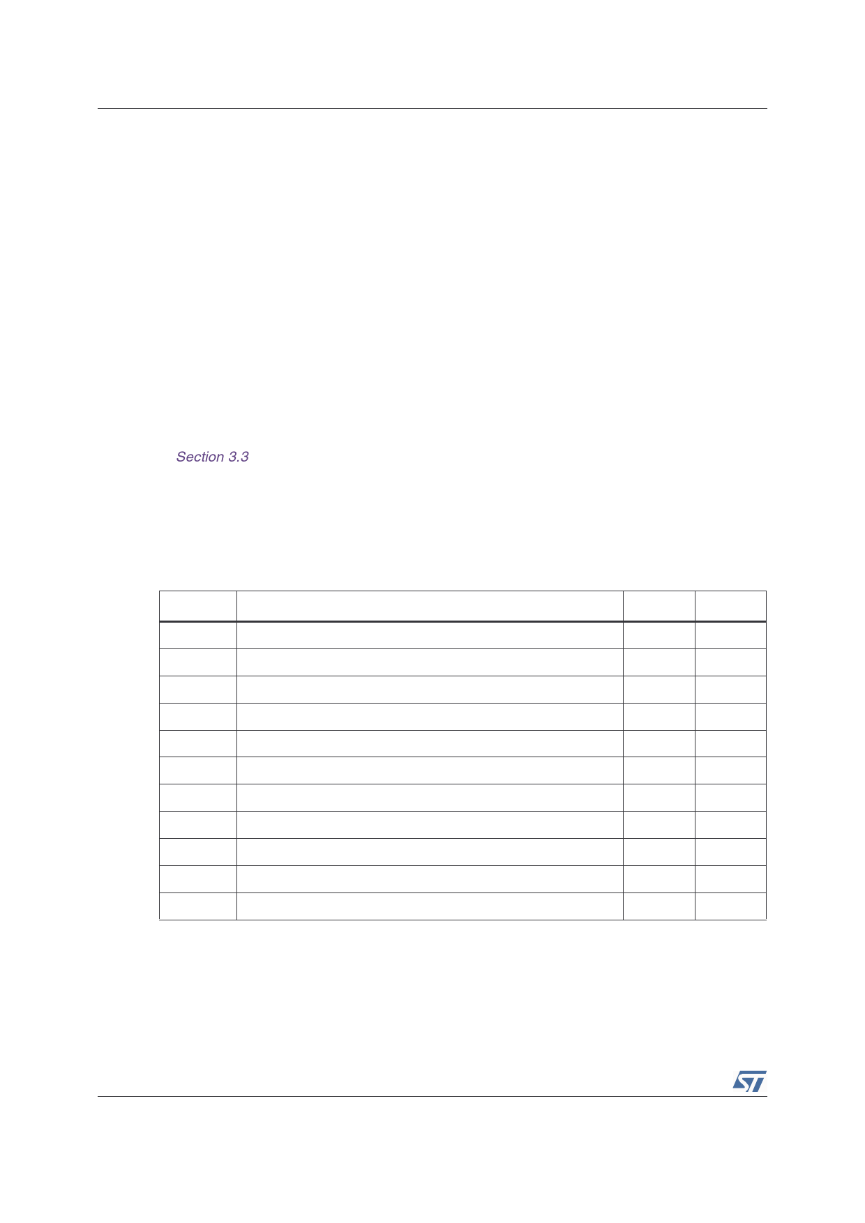
Table 5.
Electrical characteristics resulting from macromodel simulation at VCC = 3V,
VDD = 0V, RL, CL connected to VCC/2, Tamb = 25°C (unless otherwise specified)
Symbol
Conditions
Value
Unit
Vio
Avd
ICC
Vicm
VOH
VOL
Isink
Isource
GBP
SR
φm
RL = 10kΩ
No load, per operator
RL = 10kΩ
RL = 10kΩ
VO = 3V
VO = 0V
RL = 600kΩ
RL = 10kΩ, CL = 100pF
RL = 600kΩ
0
mV
200
V/mV
1.2
mA
-0.2 to 3.2
V
2.95
V
25
mV
80
mA
80
mA
4
MHz
1.3
V/µs
68
Degrees
8/14
Share Link: 