RIVA128 データシートの表示(PDF) - STMicroelectronics
部品番号
コンポーネント説明
メーカー
RIVA128 Datasheet PDF : 77 Pages
| |||
128-BIT 3D MULTIMEDIA ACCELERATOR
RIVA 128
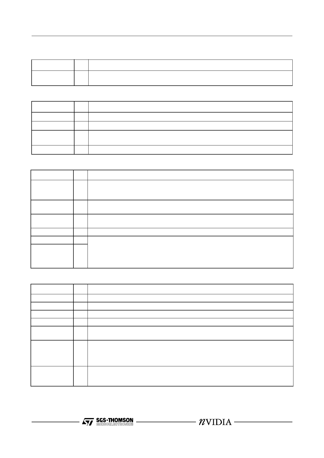
2.5 DEVICE ENABLE SIGNALS
Signal
ROMCS#
I/O Description
O Enables reads from an external 64Kx 8 or 32Kx8 ROM or Flash ROM. This signal is used
in conjunction with framebuffer data lines as described above in Section 2.3.
2.6 DISPLAY INTERFACE
Signal
I/O Description
SDA
SCL
VIDVSYNC
VIDHSYNC
I/O Used for DDC2B+ monitor communication and interface to video decoder devices.
I/O Used for DDC2B+ monitor communication and interface to video decoder devices.
O Vertical sync supplied to the display monitor. No buffering is required. In TV mode this sig-
nal supplies composite sync to an external PAL/NTSC encoder.
O Horizontal sync supplied to the display monitor. No buffering is required.
2.7 VIDEO DAC AND PLL ANALOG SIGNALS
Signal
RED,
GREEN,
BLUE
COMP
RSET
VREF
XTALIN
XTALOUT
I/O Description
O RGB display monitor outputs. These are software configurable to drive either a doubly ter-
minated or singly terminated 75Ω load.
- External compensation capacitor for the video DACs. This pin should be connected to
DACVDD via the compensation capacitor, see Figure 58, page 54.
- A precision resistor placed between this pin and GND sets the full-scale video DAC cur-
rent, see Figure 58, page 54.
- A capacitor should be placed between this pin and GND as shown in Figure 58, page 54.
I A series resonant crystal is connected between these two points to provide the reference
O clock for the internal MCLK and VCLK clock synthesizers, see Figure 58 and Table 16,
page 54. Alternately, an external LVTTL clock oscillator output may be driven into XTA-
LOUT, connecting XTALIN to GND. For designs supporting TV-out, XTALOUT should be
driven by a reference clock as described in Section 11.6, page 55.
2.8 POWER SUPPLY
Signal
DACVDD
PLLVDD
VDD
GND
MPCLAMP
HOSTVDD
HOSTCLAMP
I/O Description
P Analog power supply for the video DACs.
P Analog power supply for all clock synthesizers.
P Digital power supply.
P Ground.
P MPCLAMP is connected to +5V to protect the 3.3V RIVA 128 from external devices which
will potentially drive 5V signal levels onto the Video Port input pins.
P HOSTVDD is connected to the Vddq 3.3 pins on the AGP connector. This is the supply
voltage for the I/O buffers and is isolated from the core VDD. On AGP designs these pins
are also connected to the HOSTCLAMP pins. On PCI designs they are connected to the
3.3V supply.
P HOSTCLAMP is the supply signalling rail protection for the host interface. In AGP designs
these signals are connected to Vddq 3.3. For PCI designs they are connected to the I/O
power pins (V(I/O)).
9/77
Share Link: 