MC-4516DA727EFA-A75 データシートの表示(PDF) - NEC => Renesas Technology
部品番号
コンポーネント説明
メーカー
MC-4516DA727EFA-A75
NEC => Renesas Technology

MC-4516DA727EFA-A75 Datasheet PDF : 16 Pages
| |||
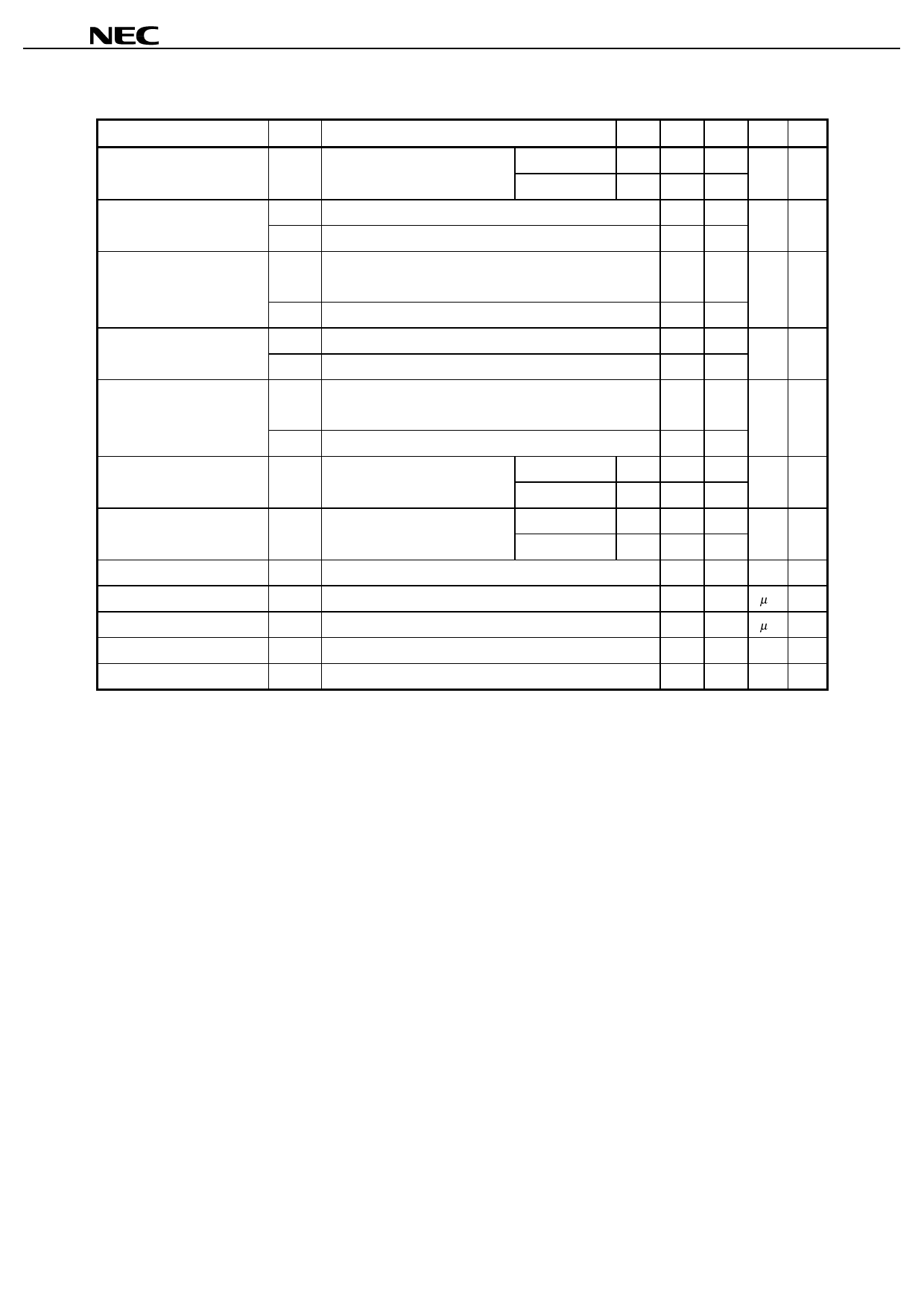
MC-4516DA727
DC Characteristics (Recommended Operating Conditions unless otherwise noted)
Parameter
Symbol
Test condition
Grade MIN. MAX. Unit Notes
5
Operating current
ICC1 Burst length = 1
/CAS latency = 2 -A75
5
tRC ≥ tRC (MIN.), IO = 0 mA
/CAS latency = 3 -A75
Precharge standby current in ICC2P CKE ≤ VIL (MAX.), tCK = 15 ns
5
power down mode
ICC2PS CKE ≤ VIL (MAX.), tCK = ∞
Precharge standby current in ICC2N CKE ≥ VIH (MIN.), tCK = 15 ns, /CS ≥ VIH (MIN.),
non power down mode
Input signals are changed one time during 30 ns.
1,300 mA 1
1,345
259 mA
89
430 mA
Active standby current in
power down mode
ICC2NS CKE ≥ VIH (MIN.), tCK = ∞, Input signals are stable.
ICC3P CKE ≤ VIL (MAX.), tCK = 15 ns
ICC3PS CKE ≤ VIL (MAX.), tCK = ∞
152
295 mA
116
Active standby current in
non power down mode
ICC3N CKE ≥ VIH (MIN.), tCK = 15 ns, /CS ≥ VIH (MIN.),
Input signals are changed one time during 30 ns.
520 mA
ICC3NS CKE ≥ VIH (MIN.), tCK = ∞, Input signals are stable.
5
Operating current
ICC4 tCK ≥ tCK (MIN.), IO = 0 mA
/CAS latency = 2 -A75
5
(Burst mode)
/CAS latency = 3 -A75
5
CBR (Auto) Refresh current
ICC5
tRC ≥ tRC (MIN.)
/CAS latency = 2 -A75
5
/CAS latency = 3 -A75
260
1,480 mA 2
1,795
2,470 mA 3
2,560
Self refresh current
Input leakage current
Output leakage current
ICC6 CKE ≤ 0.2 V
II (L) VI = 0 to 3.6 V, All other pins not under test = 0 V
IO (L) DOUT is disabled, VO = 0 to 3.6 V
268 mA
–10 +10 µA
–1.5 +1.5 µA
High level output voltage
VOH IO = –4.0 mA
2.4
V
Low level output voltage
VOL IO = +4.0 mA
0.4 V
Notes 1. ICC1 depends on output loading and cycle rates. Specified values are obtained with the output open. In
addition to this, ICC1 is measured on condition that addresses are changed only one time during tCK (MIN.).
2. ICC4 depends on output loading and cycle rates. Specified values are obtained with the output open. In
addition to this, ICC4 is measured on condition that addresses are changed only one time during tCK (MIN.).
3. ICC5 is measured on condition that addresses are changed only one time during tCK (MIN.).
6
Data Sheet M14082EJ4V0DS00
Share Link: