CY7C9335(1999) データシートの表示(PDF) - Cypress Semiconductor
部品番号
コンポーネント説明
メーカー
CY7C9335 Datasheet PDF : 7 Pages
| |||
CY7C9335
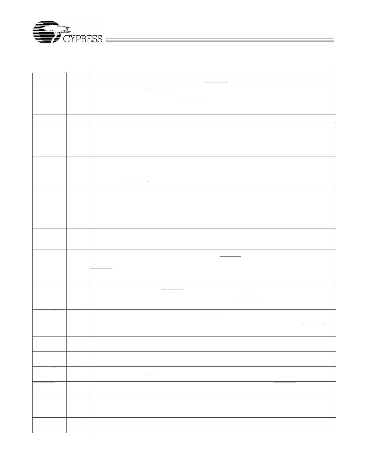
Pin Descriptions
CY7C9335 SMPTE-259M Decoder
Name
BYPASS
I/O
Input
RF
Output
A/B
Output
H_SYNC Output
SYNC_EN Input
SYNC_ERR Output
PD9(RVS) Output
PD8−1
Output
PD0(SC/D) Output
D9(RVS)
D8−1
D0(SC/D)
DVB_EN
Input
Input
Input
Input
CKR
Input
OE
Input
Description
Bypass SMPTE decoding. BYPASS is ignored if DVB_EN is active (LOW). If BYPASS is HIGH at the
rising edge of CKR (and DVB_EN is HIGH), the data latched into the input register is routed around both
the NRZI decoder and the SMPTE descrambler and presented to the output register. If BYPASS is LOW
at the rising edge of the CKR clock (and DVB_EN is HIGH), the data present in the input register is routed
through the NRZI decoder and SMPTE scrambler.
Reframe. This output is the inverted DVB-EN signal.
CY7B9334 Port Select. When in DVB-ASI mode, this output will alternately select either the INA± or INB±
receiver port based on errors detected in the data stream. This allows CY7C9335 to operate with normal
and inverted DVB-ASI data streams (as would be commonly found on DVB-ASI streams routed through
SMPTE switches). This requires the CY7B9334 INA± and INB± inputs to be connected to the same
signal, but with INB± connected to invert the signal.
Horizontal Sync. This output toggles once every time that the TRS field is recognized. It changes state
one clock cycle prior to the first character of the TRS field (3FF in 10-bit hex) appearing at the PD0−9
outputs. This output also toggles to indicate detection of a TRS sequence, even when the TRS characters
are at a different offset from the present offset and SYNC_EN is active (HIGH). This toggling action is
disabled when DVB_EN is active (LOW).
Sync Filtering Enabled. This input controls the operation of the SMPTE framer. When this signal is active
(HIGH) and a TRS sequence is detected, if the 10-bit character boundary is different from the previously
received TRS, the H_SYNC output is toggled, but the character offset is not updated. If the immediately
following TRS also has a different offset, the H_SYNC output is again toggled and the character offset
is updated to match that of the detected TRS sequence. When this signal is inactive (LOW), the framer
will update the character offset and toggle H_SYNC on every detected TRS sequence.
Sync Error. This output pulses HIGH for one CKR clock period when a TRS sequence is detected that
is offset from its previous 10-bit character offset. This pulse starts at the same time as the H_SYNC signal
toggles, but only occurs when SYNC_EN is active (HIGH) and the character offset is not updated.
Parallel Data 9 or Received Violation Symbol. This is the MSB of the framed output data bus. It is latched
in the output register at the rising edge of CKR. When DVB_EN is active (LOW), this output indicates
that the character present on PD8−0 identifies the type of error detected in the character stream. When
DVB_EN is disabled (HIGH), the character in the output register bits PD9−0 is a descrambled and framed
character of the SMPTE data stream.
Parallel Data 8 through 1. The signals present at the PD8−1 outputs are latched in the output register at
the rising edge of CKR. When DVB_EN is disabled (HIGH), these signals are the middle eight bits of the
descrambled and framed SMPTE 10-bit data character. When DVB_EN is active (LOW), these signals
are full DVB-ASI data bus.
Parallel Data 0 or Special Code/Data Select. This is the LSB of the output data field. It is latched in the
output register at the rising edge of CKR. When DVB_EN is active (LOW), this output identifies that the
character present in PD8−1 is either a command (HIGH) or data (LOW) character). When DVB_EN is
inactive (HIGH), this output data bit is the LSB of the descrambled and framed SMPTE data character.
Input Bit 9. This is the MSB of the input register. It should be connected directly to the CY7B9334
deserializer output signal RVS(Qj).
Input Bits 8 through 1. These signals should be connected directly to the CY7B9334 deserializer output
signals Q7−0 respectively.
Input Bit 0. This is the LSB of the input register. It should be connected directly to the CY7B9334 dese-
rializer output signal SC/D(Qa).
DVB Mode Enable. This signal is sampled by the rising edge of the CKR clock. If DVB_EN is active (LOW),
the data present on the D0−9 inputs are latched and routed to the PD0−9 outputs.
Recovered Clock Read. This clock controls all synchronous operations of the CY7C9335. It operates at
the character rate which is equivalent to one tenth the deserialized bit-rate. This clock is driven directly
by the CKR output of the CY7B9334 deserializer.
Output Enable. When this signal is HIGH all outputs are driven to their normal logic levels. When LOW,
all outputs are placed in a High-Z state.
3
Share Link: 