NJG1519KC1 データシートの表示(PDF) - Japan Radio Corporation
部品番号
コンポーネント説明
メーカー
NJG1519KC1 Datasheet PDF : 16 Pages
| |||
NJG1519KC1
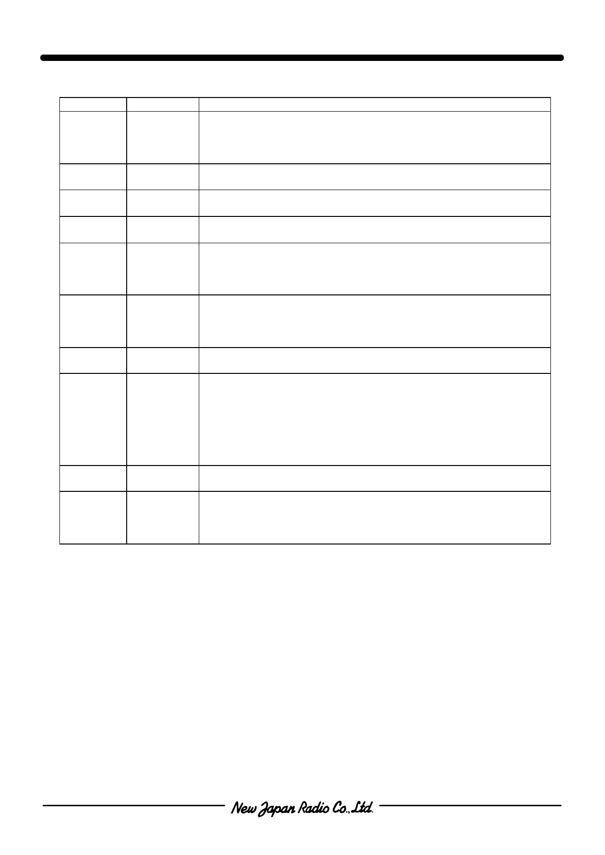
nTERMINAL INFORMATION
No.
SYMBOL
EXPLANATION
RF port. This terminal is connected under the condition of
1
P1
2pin-VCTL(H) (+2.5~+6.5V), 4, 7, 9pin-VCTL(L) (-0.2~+0.2V).
A DC cut capacitor 56pF is reguired at this terminal to block DC
voltage of inner circuit.
2
VCTL1
Control port1. Please connect bypass capacitor (10pF) between this
terminal and GND close to this IC.
3
GND
Ground terminal. Please connect this terminal with ground plane as
close as possible for excellent RF performance.
4
VCTL2
Control port2. Please connect bypass capacitor (10pF) between this
terminal and GND close to this IC.
RF port. This terminal is connected under the condition of
5
P2
4pin-VCTL(H) (+2.5~+6.5V), 2, 7, 9pin-VCTL(L) (-0.2~+0.2V).
A DC cut capacitor 56pF is reguired at this terminal to block DC
voltage of inner circuit.
RF port. This terminal is connected under the condition of
6
P3
7pin-VCTL(H) (+2.5~+6.5V), 2, 4, 9pin-VCTL(L) (-0.2~+0.2V).
A DC cut capacitor 56pF is reguired at this terminal to block DC
voltage of inner circuit.
7
VCTL3
Control port3. Please connect bypass capacitor (10pF) between this
terminal and GND close to this IC.
Common RF port. This terminal is connected by the control voltage
supplied to each control terminal (VCTL1~VCTL4 terminal). Please
see the description of each terminal. A DC cut capacitor (56pF) is
8
PC
reguired at this terminal to block DC voltage of inner circuit.
This terminal and GND are connected by high resistance (200KΩ) to
avoid unexpected signal output that is possibly generated right after
burst signal switching.
9
VCTL4
Control port4. Please connect bypass capacitor (10pF) between this
terminal and GND close to this IC.
RF port. This terminal is connected under the condition of
10
P4
9pin-VCTL(H) (+2.5~+6.5V), 2, 4, 7pin-VCTL(L) (-0.2~+0.2V).
A DC cut capacitor 56pF is reguired at this terminal to block DC
voltage of inner circuit.
-3-
Share Link: 