NJM3717D2 データシートの表示(PDF) - Japan Radio Corporation
部品番号
コンポーネント説明
メーカー
NJM3717D2 Datasheet PDF : 10 Pages
| |||
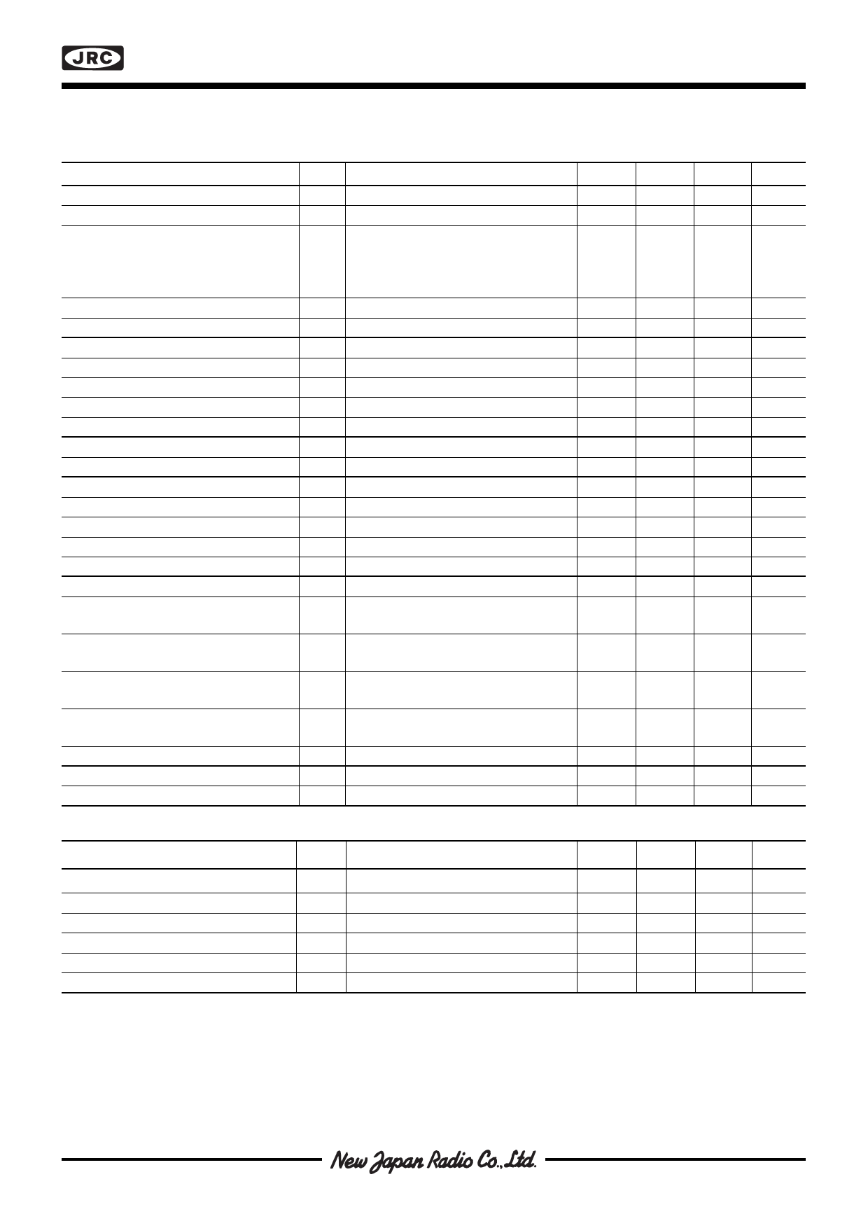
NJM3717
s ELECTRICAL CHARACTERISTICS
Electrical characteristics over recommended operating conditions, unless otherwise noted -20°C≤ TJ≤ +125°C.
CT = 820 pF, RT = 56 kohm.
Parameter
General
Symbol
Conditions
Min
Typ
Max
Supply current
Total power dissipation
ICC
-
-
25
P f = 28 kHz, I = 500mA, V = 36 V
-
1.4
1.7
D
s
M
MM
Note 2, 4.
fs = 28 kHz, IM = 800mA, VMM = 36 V
-
2.8
3.3
Note 3, 4.
Turn-off delay
td
Thermal shutdown junction temperature
Ta = +25°C, dVC/dt ≥ 50 mV/µs.
-
0.9
1.5
-
170
-
Logic Inputs
Logic HIGH input voltage
Logic LOW input voltage
Logic HIGH input current
Logic LOW input current
Reference Input
VIH
VIL
IIH VI = 2.4 V
IIL VI = 0.4 V
2.0
-
-
-
-
0.8
-
-
20
-0.4
-
-
Input resistance
Comparator Inputs
RR Ta = +25°C
-
6.8
-
Threshold voltage
Threshold voltage
Threshold voltage
Input current
Motor Outputs
VCH VR = 5.0 V, I0 = I1 = LOW
VCM VR = 5.0 V, I0 = HIGH, I1 = LOW
VCL VR = 5.0 V, I0 = LOW, I1 = HIGH
IC
400
415
430
240
250
265
70
80
90
-20
-
-
Lower transistor saturation voltage
Lower diode forward voltage drop
Upper transistor saturation voltage
Upper diode forward voltage drop
Output leakage current
Monostable
IM = 500 mA
IM = 800 mA
IM = 500 mA
I = 800 mA
M
IM = 500 mA
IM = 800 mA
IM = 500 mA
IM = 800 mA
I = I = HIGH,
01
T
a
=
+25°C
-
0.9
1.2
-
1.1
1.4
-
1.2
1.5
-
1.3
1.7
-
1.0
1.25
-
1.2
1.5
-
1.0
1.25
-
1.2
1.45
-
-
100
Cut off time
toff VMM = 10 V, ton ≥ 5 µs
27
31
35
s THERMAL CHARACTERISTICS
Unit
mA
W
W
µs
°C
V
V
µA
mA
kohm
mV
mV
mV
µA
V
V
V
V
V
V
V
V
µA
µs
Parameter
Thermal resistance
Symbol
Conditions
Rthj-GND
RthJ-A
Rthj-
GND
RthJ-A
Rthj-GND
RthJ-A
DIP package.
DIP package. Note 2.
PLCC package.
PLCC package. Note 2.
EMP package
EMP package
Min
Typ
Max
Unit
-
11
-
°C/W
-
40
-
°C/W
-
9
-
°C/W
-
35
-
°C/W
-
11
-
°C/W
-
40
-
°C/W
Notes
1. All voltages are with respect to ground. Currents are positive into, negative out of specified terminal.
2.
3.
4.
All ground pins soldered onto a 20 cm2 PCB copper
DIP package with external heatsink (Staver V7) and
Not covered by final test program.
area with free air convection.
minimal copper area. Typical
RTtAhJ+-A2=5°2C7..5°C/W.
TA
=
+25°C.
Share Link: 