NJM3717 データシートの表示(PDF) - Japan Radio Corporation
部品番号
コンポーネント説明
メーカー
NJM3717 Datasheet PDF : 10 Pages
| |||
NJM3717
Analog control
As the current levels can be continuously controlled by modulating the VR input, limited microstepping can be
achieved.
Switching frequency
The motor inductance, together with the pulse time, toff , determines the switching frequency of the current regulator.
The choice of motor may then require other values on the RT , CT components than those recommended in figure7,
to obtain a switching frequency above the audible range. Switching frequencies above 40 kHz are not recom-
mended because the current regulation can be affected.
Sensor resistor
The RS resistor should be of a non-inductive type, power resistor. A 1.0 ohm resistor, tolerance ≤ 1%, is a good
choice for 415 mA max motor current at V = 5V.
R
The peak motor current, im , can be calculated by using the formulas:
im = (VR • 0.083) / RS [A], at 100% level
im = (VR • 0.050) / RS [A], at 60% level
im = (VR • 0.016) / RS [A], at 20% level
Heatsinking
The junction temperature of the chip highly effects the lifetime of the circuit. In high-current applications, the
heatsinking must be carefully considered.
The Rth of the NJM3717 can be reduced by soldering the ground pins to a suitable copper ground plane on the
j-a
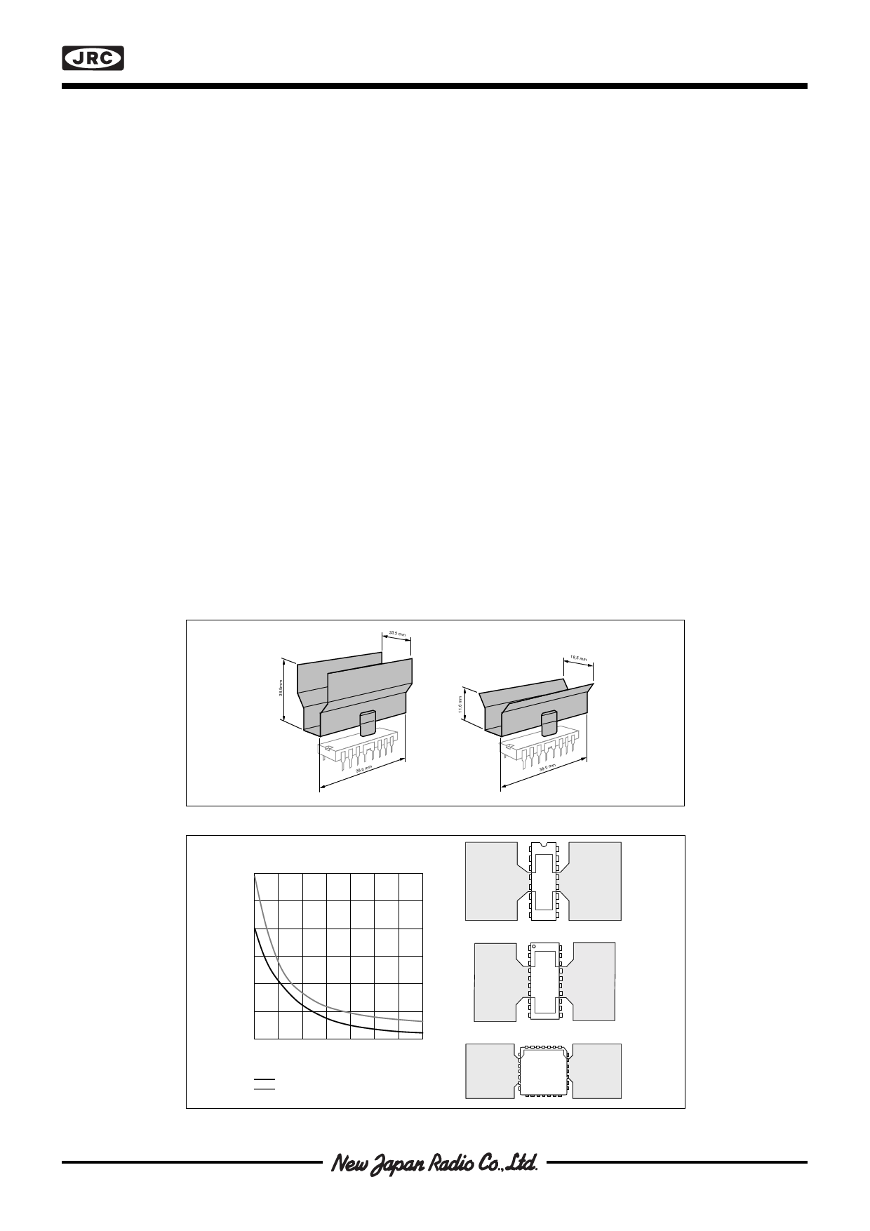
printed circuit board (see figure 10) or by applying an external heatsink type V7 or V8, see figure 9.
The diagram in figure 16 shows the maximum permissible power dissipation versus the ambient temperature in
°C, for heatsinks of the type V7, V8 or a 20 cm2 copper area respectively. Any external heatsink or printed circuit
board copper must be connected to electrical ground.
For motor currents higher than 500 mA, heatsinking is recommended to assure optimal reliability.
The diagrams in figures 9 and 10 can be used to determine the required heatsink of the circuit. In some systems,
forced-air cooling may be available to reduce the temperature rise of the circuit.
33,5 mm
18,5 mm
38.0 mm
38.0 mm
Figure 9. Heatsinks, Staver, type V7 and V8 by Columbia-Staver UK
Thermal resistance [°C/W]
90
80
70
60
50
40
30
5
10 15 20 25 30 35
PCB copper foil area [cm2 ]
PLCC package
DIP and EMP package
Figure 10. Copper foil used as a heatsink
16-pin
DIP
20-pin
EMP
28-pin
PLCC
Share Link: 