SMCJ54 „Éá„Éľ„āŅ„ā∑„Éľ„Éą„ĀģŤ°®Á§ļÔľąPDFÔľČ - Vishay Semiconductors
ťÉ®ŚďĀÁē™ŚŹ∑
„ā≥„É≥„ÉĚ„Éľ„Éć„É≥„ÉąŤ™¨śėé
„É°„Éľ„āę„Éľ
SMCJ54 Datasheet PDF : 4 Pages
| |||
SMCJ5.0 thru 188CA
Vishay Semiconductors
formerly General Semiconductor
Surface Mount TRANSZORB¬ģ
Transient Voltage Suppressors
Stand-off Voltage 5.0 to 188V
Peak Pulse Power 1500W
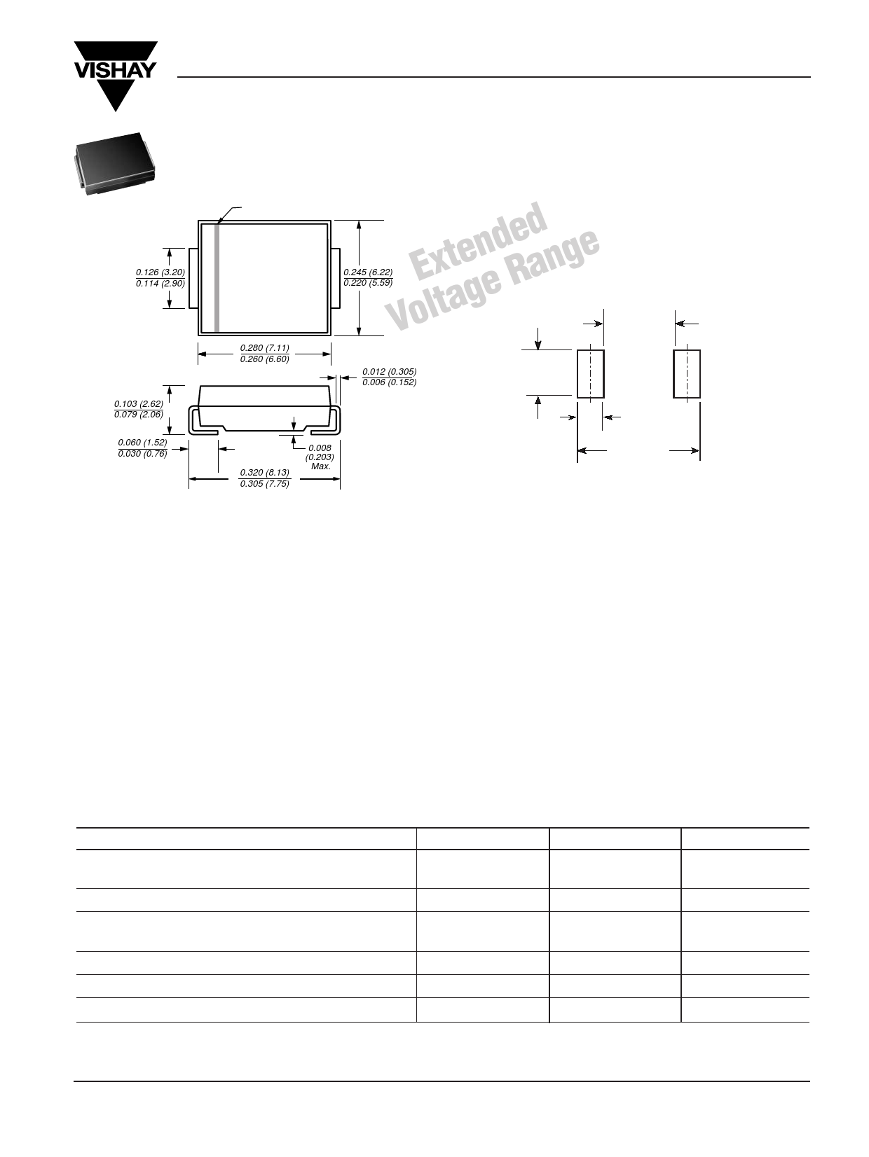
DO-214AB
(SMC J-Bend)
0.126 (3.20)
0.114 (2.90)
0.103 (2.62)
0.079 (2.06)
0.060 (1.52)
0.030 (0.76)
Cathode Band
0.280 (7.11)
0.260 (6.60)
ExtendRedange 0.245 (6.22)
Voltage 0.220 (5.59)
Mounting Pad Layout
0.185 MAX.
(4.69 MAX.)
0.012 (0.305)
0.006 (0.152)
0.121 MIN.
(3.07 MIN.)
0.320 (8.13)
0.305 (7.75)
0.008
(0.203)
Max.
Dimensions in inches
and (millimeters)
0.060 MIN.
(1.52 MIN.)
0.320 REF
Features
Mechanical Data
‚ÄĘ Underwriters Laboratory Recognition under UL standard
for safety 497B: Isolated Loop Circuit Protection
‚ÄĘ Low profile package with built-in strain relief for
surface mounted applications
‚ÄĘ Glass passivated junction
‚ÄĘ Low incremental surge resistance, excellent clamping
capability
‚ÄĘ 1500W peak pulse power capability with a 10/1000¬Ķs
waveform, repetition rate (duty cycle): 0.01%
‚ÄĘ Very fast response time
‚ÄĘ High temperature soldering guaranteed:
250¬įC/10 seconds at terminals
Case: JEDEC DO-214AB molded plastic over
passivated junction
Terminals: Solder plated, solderable per
MIL-STD-750, Method 2026
Polarity: For unidirectional types the band denotes the
cathode, which is positive with respect to the anode
under normal TVS operation
Weight: 0.007 oz., 0.21 g
Flammability: Epoxy is rated UL 94V-0
Packaging Codes ‚Äď Options (Antistatic):
51 ‚Äď 1K per Bulk box, 10K/carton
57 ‚Äď 850 per 7" plastic Reel (16mm tape), 8.5K/carton
9A ‚Äď 3.5K per 13" plastic Reel (16mm tape), 35K/carton
Devices for Bidirectional Applications
For bi-directional devices, use suffix C or CA (e.g. SMCJ10C, SMCJ10CA). Electrical characteristics apply in both directions.
Maximum Ratings & Thermal Characteristics Ratings at 25¬įC ambient temperature unless otherwise specified.
Parameter
Symbol
Value
Unit
Peak pulse power dissipation with
a 10/1000¬Ķs waveform(1)(2)
Peak pulse current with a 10/1000¬Ķs waveform(1)
Peak forward surge current 8.3ms single half sine-wave (2)
uni-directional only
Typical thermal resistance, junction to ambient (3)
Typical thermal resistance, junction to lead
Operating junction and storage temperature range
PPPM
IPPM
IFSM
RőłJA
RőłJL
TJ, TSTG
Minimum 1500
See Next Table
200
75
15
‚Äď55 to +150
W
A
A
¬įC/W
¬įC/W
¬įC
Notes: (1) Non-repetitive current pulse, per Fig.3 and derated above TA = 25¬įC per Fig. 2
(2) Mounted on 0.31 x 0.31‚ÄĚ (8.0 x 8.0mm) copper pads to each terminal
(3) Mounted on minimum recommended pad layout
Document Number 88394
26-Sep-02
www.vishay.com
1
Share Link: 