LZ93N19 データシートの表示(PDF) - Sharp Electronics
部品番号
コンポーネント説明
メーカー
LZ93N19 Datasheet PDF : 11 Pages
| |||
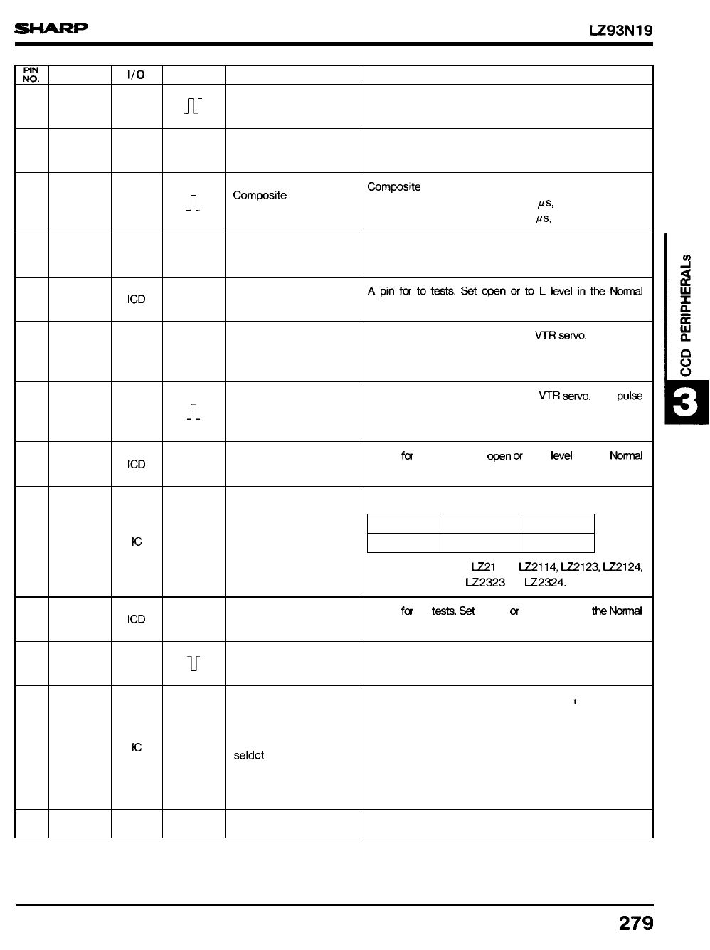
LZ93N19
::, SYMBOL
14
LSW
15
ENCP
16
CBLK
17 CSYNC
18
TST5
19
FRP2
20
FRPI
21
TST2
22 CKMD
23
TST4
24
HBLK
25 CPMD
26
GND
1/0 POLARITY
PIN NAME
o
N
Line switch
o
n
Encoder DC clamp
FUNCTION
The signal switches between H and L at every line.
It is set at Low level at the 1st line of the 1st field.
A clamp pulse that is used for recovering DC level.
The repetition is horizontal frequency.
Compcsite blanking pulses.
o
timposite blanking
n
pulse
In NTSC mode; H : 11.01 ps, V : 20 H period
In PAL mode ; H : 12.12 MS, V : 25 H period
o
v
Composite synchronous
A composite synchronous signal.
signal
ICD
—
Test terminal 5
Apinfor totests, Setopenorto Llwel inthem
mode.
o
n
Frame read pulse 2
A clock output that is used for VTR =rvo. The pulse
occurs at even fields and its repetition is frame
period.
A clock output that is used for VTR seNo. The PUIS
o
n
Frame read pulse 1
occurs at odd fields and its repetition is frame
period.
ICD
—
Test terminal 2
A pin fm to tests. Set ~n w to L Iwel in the Mti
mode.
A pin to select the factor of frequeny divisions,
Ic
—
Clock mode select
Division
CKMD
1/3
LOW
1/4
HIGH
Set to L level for ml 13, LZ2114, ~123, ~124,
U2313, LZ2314, LZ2323 or U2324.
ICD
–
Test terminal 4
A pin f(x to t=ts. % open of to L level in h M
mode.
o
Horizontal blanking
A pulse that corresponds to the cease period of
u
pulse
the horizontal transfer pulse.
An input pin to stop or continue BCP I (pin 37) and
BCP2 (pin 38) pulses within the vertical blanking
period.
Ic
—
Clamp Pulse mode
L level : continuous output.
seldct
H level : becomes Low level during the ab-
sence of effective pixels within V
blanking period.
–
–
Grounding
A grounding pin.
279
Share Link: 