NE56604-42D データシートの表示(PDF) - Philips Electronics
部品番号
コンポーネント説明
メーカー
NE56604-42D Datasheet PDF : 17 Pages
| |||
Philips Semiconductors
System reset with built-in Watchdog timer
Product data
NE56604-42
Application information
The Watchdog timer’s external component values are critical to its
performance.
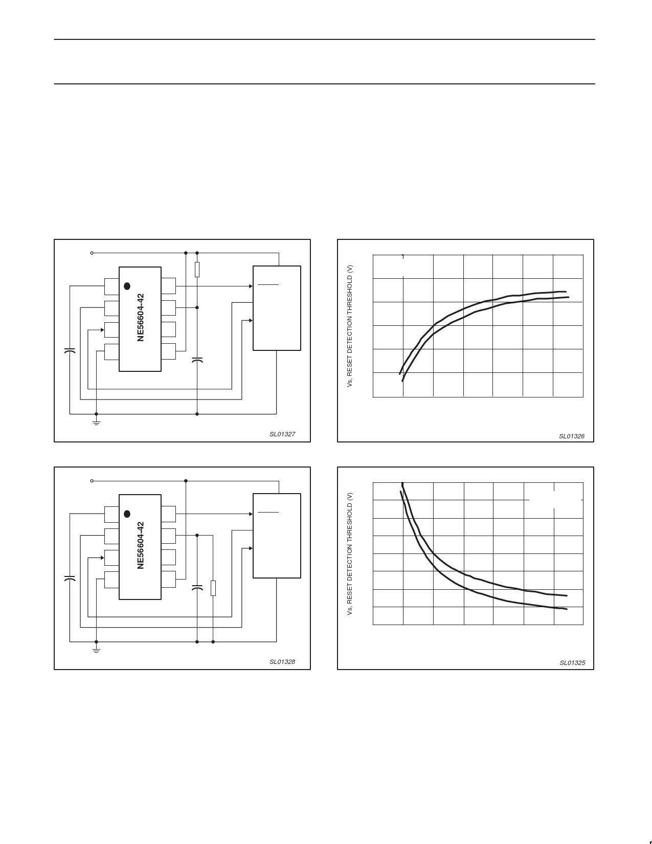
The detection threshold voltage can be adjusted by externally
influencing the internal divider reference voltage. Figures 21 and 23
show a method to lower and raise the threshold voltage. Figures 22
and 24 show the influence of the pull-down and pull-up resistors on
the threshold voltage. The use of a capacitor (1000 pF or larger)
from Pin 7 to ground is recommended to filter out noise from being
imposed on the threshold voltages.
VCC
1
2
3
CT
4
R1
8
7
6
5
1000 pF
LOGIC SYSTEM
RESET
CLK
RESET
GND
SL01327
Figure 21. Circuit to lower detection threshold.
VCC
1
2
3
CT
4
8
7
6
5
1000 pF
LOGIC SYSTEM
RESET
CLK
RESET
GND
R2
SL01328
Figure 23. Circuit to raise detection threshold.
The Reset Detection Threshold can be decreased by connecting an
external resistor R1 from Pin 7 to VCC, as shown in Figure 21. See
Figure 22 to determine the approximate value of R1 to use.
The Reset Detection Threshold can be increased by connecting an
external resistor R2 from Pin 7 to ground, as shown in Figure 23.
See Figure 24 to determine the approximate value of R2 to use.
5.0
VCC = 5.0 V
Tamb = 25 °C
4.0
3.5
VSH
VSL
3.0
0
100
200
300
400
500
600
700
R1, EXTERNAL PIN 7 TO VCC RESISTOR (kΩ)
SL01326
Figure 22. Reset detection threshold vs. external R1.
5.1
5.0
VCC = 5.0 V
Tamb = 25 °C
4.9
4.8
4.7
4.6
VSH
4.5
VSL
4.4
4.3
0
100
200
300
400
500
600
700
R2, EXTERNAL PIN 7 TO GROUND RESISTOR (kΩ)
SL01325
Figure 24. Reset detection threshold vs. external R2.
2003 Oct 15
11
Share Link: 