74VHC27 データシートの表示(PDF) - STMicroelectronics
部品番号
コンポーネント説明
メーカー
74VHC27 Datasheet PDF : 10 Pages
| |||
74VHC27
Table 8: Capacitive Characteristics
Symbol
Parameter
CIN Input Capacitance
CPD Power Dissipation
Capacitance
(note 1)
Test Condition
Value
TA = 25°C
-40 to 85°C -55 to 125°C Unit
Min. Typ. Max. Min. Max. Min. Max.
6 10
10
10 pF
17
pF
1) CPD is defined as the value of the IC’s internal equivalent capacitance which is calculated from the operating current consumption without
load. (Refer to Test Circuit). Average operating current can be obtained by the following equation. ICC(opr) = CPD x VCC x fIN + ICC/3 (per gate)
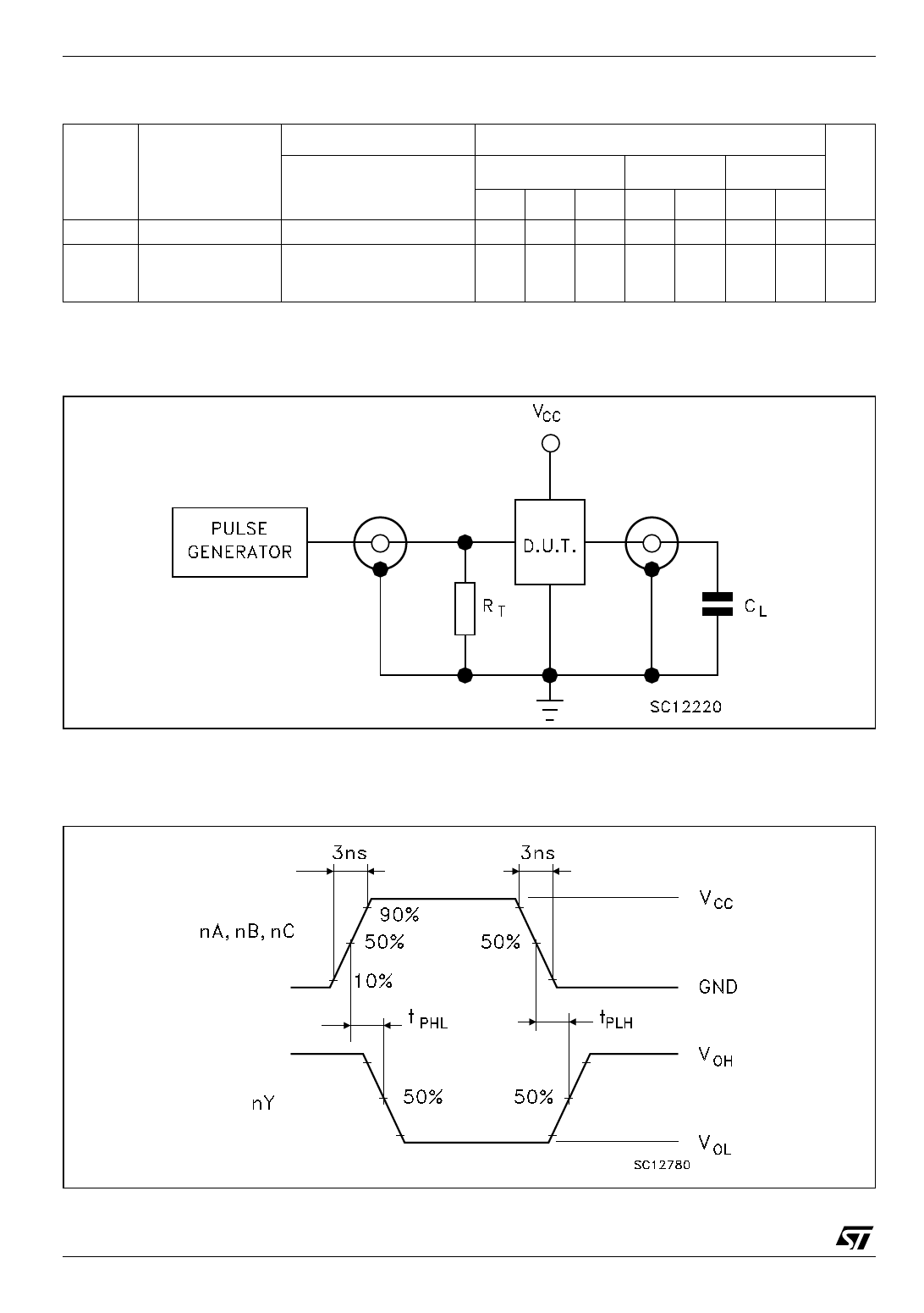
Figure 3: Test Circuit
CL =15/50pF or equivalent (includes jig and probe capacitance)
RT = ZOUT of pulse generator (typically 50Ω)
Figure 4: Waveform - Propagation Delays (f=1MHz; 50% duty cycle)
4/10
Share Link: 