TX2-1.5V データシートの表示(PDF) - Panasonic Corporation
部品番号
コンポーネント説明
メーカー
TX2-1.5V
Panasonic Corporation

TX2-1.5V Datasheet PDF : 7 Pages
| |||
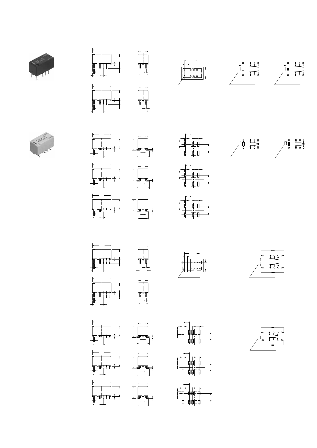
DIMENSIONS
1. Single side stable and 1 coil latching type
Standard PC board terminal
15
.591
0.5
.020
1.15 5.08
.045 .200
0.65 8.2
.026 .323
3.5
.138
2.54
.100
7.4
.291
0.25
5.08 .010
.200
Self clinching terminal
Surface-mount terminal
SA type
SL type
SS type
15
.591
7.4
.291
0.65 8.2
.026 .323
3.5
.138
0.5
.020
1.15 5.08
2.54
.045 .200
.100
0.25
5.08 .010
.200
General tolerance: ±0.3 ±.012
15
.591
7.4
.291
8.2
.323
0.5
.020
0.65
5.08
.200
2.54 .026
.100
15
.591
8.4
.331
5.08
.200
9.4±0.5
.370±.020
0.25
.010
7.4
.291
8.2
.323
0.5
.020
0.65
5.08
2.54 .026
.200 .100
15
.591
Max.
10.0
.390
5.08
.200
9.4±0.5
0.25
.010
.370±.020
7.4
.291
8.2
Max.
.323
10.0
.390
0.5
.020
0.65
5.08
.200
2.54 .026
.100
5.08
.200
0.25
.010
7.4±0.5
.291±.020
General tolerance: ±0.3 ±.012
PC board pattern
(Copper-side view)
10.16
2.54
.400
.100
5.08
.200
8-1.0 dia
8-.039 dia
Tolerance: ±0.1 ±.004
TX
mm inch
Schematic (Bottom view)
Single side stable
1 coil latching
(Deenergized condition) (Reset condition)
1 345
+
1 345
–
–
12 10 9 8
+
12 10 9 8
Direction indication*
Direction indication*
*Orientation stripe located on top of relay.
Suggested mounting pad
(Top view)
1 5.08 2.54
.039 .200 .100
3.16
.124
7.24
.285
Schematic (Top view)
Single side stable
1 coil latching
(Deenergized condition) (Reset condition)
– 12 10 9 8
+ 12 10 9 8
+
1 345
Direction indication
–
1 345
Direction indication
1 5.08 2.54
.039 .200 .100
3.16
.124
7.24
.285
1 5.08 2.54
.039 .200 .100
2.16
.085
6.24
.246
Tolerance: ±0.1 ±.004
2. Coil latching type
Standard PC board terminal
15
.591
7.4
.291
Self clinching terminal
0.65 8.2
.026 .323
3.5
.138
0.5
.020
1.15 5.08
2.54
.045 .200
.100
15
.591
0.25
5.08 .010
.200
7.4
.291
Surface-mount terminal
SA type
0.65 8.2
.026 .323
3.5
.138
0.5
.020
1.15 5.08
2.54
.045 .200
.100
0.25
5.08 .010
.200
General tolerance: ±0.3 ±.012
15
.591
7.4
.291
PC board pattern
(Copper side view)
12.7
2.54
.500
.100
5.08
.200
10-1.0 dia
10-.039 dia
Tolerance: ±0.1 ±.004
Suggested mounting pad (Top view)
1 5.08
2.54
.039 .200
.100
8.2
.323
8.4
.331
3.16
.124
7.24
0.5
5.08
.285
.020
0.65
5.08
2.54 .026
.200 .100
.200
9.4±0.5
.370±.020
0.25
.010
SL type
SS type
15
.591
7.4
.291
8.2
.323
0.5
.020
0.65
5.08
.200
2.54 .026
.100
15
.591
Max.
10.0
.390
5.08
.200
9.4±0.5
0.25
.010
.370±.020
7.4
.291
8.2
Max.
.323
10.0
.390
0.5
.020
0.65
5.08
.200
2.54 .026
.100
5.08
.200
0.25
.010
7.4±0.5
.291±.020
General tolerance: ±0.3 ±.012
1 5.08
2.54
.039 .200
.100
3.16
.124
7.24
.285
1 5.08
2.54
.039 .200
.100
2.16
.085
6.24
.285
Tolerance: ±0.1 ±.004
Schematic (Bottom view)
2 coil latching (Reset condition)
1 3 456
+
–
+
–
12 10 9 8 7
Direction indication*
Schematic (Top view)
2 coil latching (Reset condition)
12 10 9 8 7
+
–
+
–
1 345 6
Direction indication
All Rights Reserved © COPYRIGHT Matsushita Electric Works, Ltd.
Share Link: