NTE6401 データシートの表示(PDF) - NTE Electronics
部品番号
コンポーネント説明
メーカー
NTE6401 Datasheet PDF : 2 Pages
| |||
Electrical Characteristics (Cont’d): (TA = +25°C unless otherwise specified)
Parameter
Symbol
Test Conditions
Min Typ Max Unit
Emitter Saturation Voltage
VEB1(sat) VB2B1 = 10V, IE = 50mA, Note 4 – 3.5 –
V
Modulated Interbase Current
Emitter Reverse Current
Peak Point Emitter Current
Valley Point Current
IB2(mod)
IEB20
IP
IV
VB2B1 = 10V, IE = 50mA
VB2E = 30V, IB1 = 0
VB2B1 = 25V
VB2B1 = 20V, RB2 = 100Ω
– 15 – mA
– 0.005 12 µA
–
1
5 µA
4
6
– mA
Base–One Peak Pulse Voltage
VOB1
3
5
–
V
Note 4. Use pulse techniques: Pulse Width ~ 300µs, duty cycle ≤ 2% to avoid internal heating due
to interbase modulation which may result in erroneous readings.
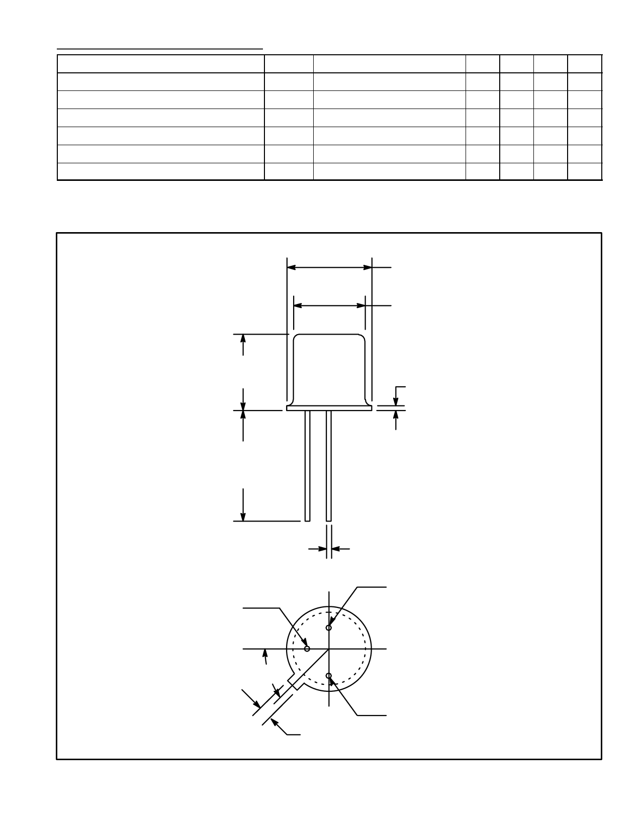
.230 (5.84) Dia Max
.195 (4.95) Dia Max
.210 (5.33)
Max
.030 (.762) Max
.500
(12.7)
Min
Emitter
.018 (0.45)
Base 1
45°
.041 (1.05)
Base 2/Case
Share Link: 