RF2510 データシートの表示(PDF) - RF Micro Devices
部品番号
コンポーネント説明
メーカー
RF2510 Datasheet PDF : 10 Pages
| |||
Preliminary
RF2510
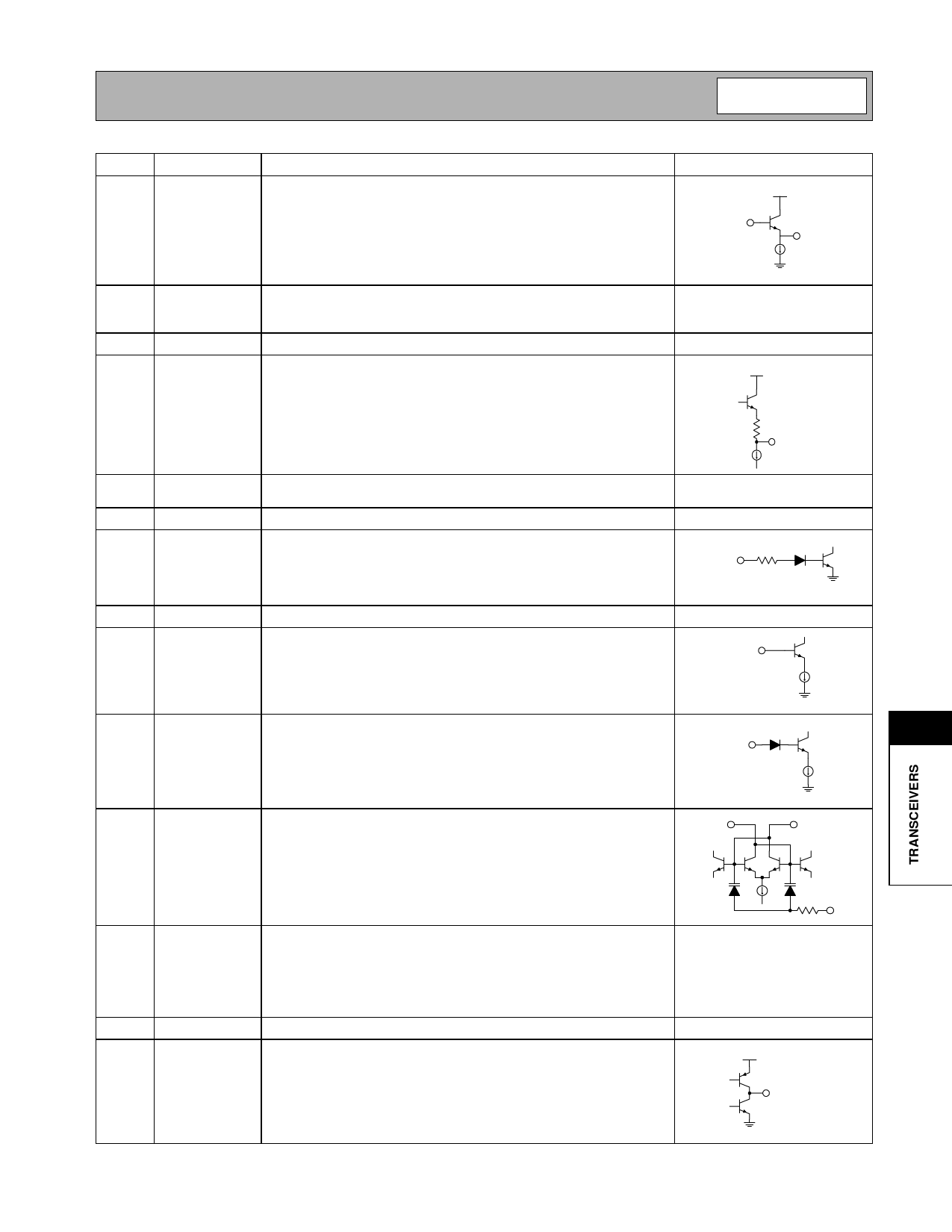
Pin Function Description
Interface Schematic
1
OSC B
This pin is connected directly to the reference oscillator transistor base.
The intended reference oscillator configuration is a modified Colpitts.
VCC2
An appropriate capacitor as chosen by the customer should be con-
nected between pin 1 and pin 2.
OSC B
OSC E
2
OSC E
This pin is connected directly to the emitter of the reference oscillator See pin 1.
transistor. An appropriate capacitor as chosen by the customer should
be connected from this pin to ground.
3
GND1
Ground connection for the VCO OUT buffer amp.
4
VCO OUT Buffered output of the VCO
VCC
20
VCO OUT
5
VCC
This pin is used to supply DC bias to the entire IC. ARF Bypass capac-
itor should be connected directly to ground.
6
GND
Ground connection.
7
PD
Power Down control for all circuitry. When this pin is a logic “low” all cir-
cuits are turned off.
PLL ENABL
50 kΩ
8
NC
Not internally connected.
9
MOD CTRL This pin is used to select the prescaler modulus. A logic “high” selects
64 or 128 for the prescaler divisor. A logic “low” selects 65 or 129 for
the prescaler divisor.
MOD CTL
10
DIV CTRL This pin is used to select the desired prescaler divisor. A logic “high”
selects the 64/65 divisor. A logic low selects the 128/129 divisor.
DIV CTL
11
11
RESNTR- The RESNTR pins are used to supply DC voltage to the VCO, as well RESNTR+
as to tune the center frequency of the VCO. Equal value inductors
should be connected to this pin and pin 13.
RESNTR-
12
MOD IN FM analog or digital modulation can be imparted to the VCO through See pin 11.
this pin. The VCO varies in accordance to the voltage level presented
to this pin. To set the deviation to a desired level, a voltage divider refer-
enced to Vcc is recommended. Because the modulation varactors are
part of the resonator tank, the deviation is slightly dependent upon the
components used in the external tank.
13 RESNTR+ See pin 11.
See pin 11.
14
LOOP FLT Output of the charge pump. An RC network from this pin to ground is
used to establish the PLL bandwidth.
VCC
4 kΩ
MOD IN
LOOP FLT
Rev A6 010207
11-3
Share Link: 