HV9910P データシートの表示(PDF) - Supertex Inc
部品番号
コンポーネント説明
メーカー
HV9910P Datasheet PDF : 11 Pages
| |||
HV9910
example, a potentiometer connected between VDD
and ground can program the control voltage at the
CS pin. Applying a control voltage higher than
250mV will not change the output current setting.
When higher current is desired, select a smaller
sense resistor.
The PWM dimming scheme can be implemented by
applying an external PWM signal to the PWM_D
pin. The PWM signal can be generated by a
microcontroller or a pulse generator with a duty
cycle proportional to the amount of desired light
output. This signal enables and disables the
converter modulating the LED current in the PWM
fashion. In this mode, LED current can be in one of
the two states: zero or the nominal current set by
the current sense resistor. It is not possible to use
this method to achieve average brightness levels
higher than the one set by the current sense
threshold level of the HV9910. By using the PWM
control method of the HV9910, the light output can
be adjusted between zero and 100%. The accuracy
of the PWM dimming method is limited only by the
minimum gate pulse width, which is a fraction of a
percent of the low frequency duty cycle.
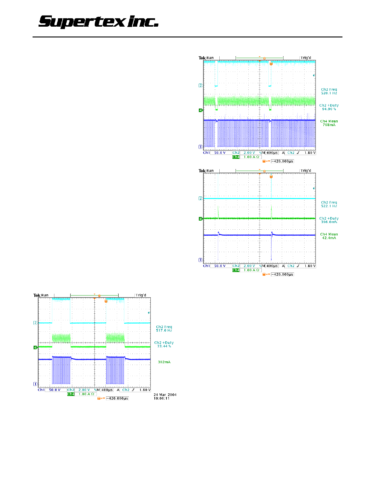
Some of the typical waveforms illustrating the PWM
dimming method used with the application circuit of
Figure 1 are given below. CH1 shows the MOSFET
Drain voltage, CH2 is the PWM signal to pin
PWM_D and CH4 is the current in the LED string.
33% PWM Ratio at 500Hz Dimming
95% PWM Ratio at 500Hz Dimming
0.4% PWM Ratio at 500Hz Dimming
Programming Operating Frequency
The operating frequency of the oscillator is
programmed between 25 and 300kHz using an
external resistor connected to the ROSC pin:
FOSC = 25000/(ROSC [kΩ] + 22) [kHz]
Power Factor Correction
When the input power to the LED driver does not
exceed 25W, a simple passive power factor
correction circuit can be added to the HV9910
application circuit of Figure 1 in order to pass the
AC line harmonic limits of the EN61000-3-2
standard for Class C equipment. The typical
application circuit diagram shows how this can be
done without affecting the rest of the circuit
significantly. A simple circuit consisting of 3 diodes
and 2 capacitors is added across the rectified AC
line input to improve the line current harmonic
distortion and to achieve a power factor greater
than 0.85.
5
C110504
Share Link: 