MAX3232CSE(1999) гғҮгғјгӮҝгӮ·гғјгғҲгҒ®иЎЁзӨәпјҲPDFпјү - Maxim Integrated
йғЁе“Ғз•ӘеҸ·
гӮігғігғқгғјгғҚгғігғҲиӘ¬жҳҺ
гғЎгғјгӮ«гғј
MAX3232CSE
(Rev.:1999)
(Rev.:1999)
3.0V to 5.5V, Low-Power, up to 1Mbps, True RS-232 Transceivers Using Four 0.1ВөF External Capacitors
Maxim Integrated

MAX3232CSE Datasheet PDF : 16 Pages
| |||
3.0V to 5.5V, Low-Power, up to 1Mbps, True RS-232
Transceivers Using Four 0.1ВөF External Capacitors
Table 1. MAX3222/MAX3237/MAX3241
Shutdown and Enable Control Truth Table
SHDN
EN
0
0
0
1
1
0
1
1
T_OUT
High-Z
High-Z
Active
Active
R_OUT
Active
High-Z
Active
High-Z
R_OUTB
(MAX3237/
MAX3241)
Active
Active
Active
Active
Table 2. Required Minimum Capacitor Values
VCC
C1
(V)
(ВөF)
MAX3222/MAX3232/MAX3241
3.0 to 3.6
0.1
4.5 to 5.5
0.047
3.0 to 5.5
0.1
MAX3237
3.0 to 3.6
0.22
3.15 to 3.6
0.1
4.5 to 5.5
0.047
3.0 to 5.5
0.22
C2, C3, C4
(ВөF)
0.1
0.33
0.47
0.22
0.1
0.33
1.0
Power-Supply Decoupling
In most circumstances, a 0.1ВөF bypass capacitor is
adequate. In applications that are sensitive to power-
supply noise, decouple VCC to ground with a capacitor
of the same value as charge-pump capacitor C1. Connect
bypass capacitors as close to the IC as possible.
Operation Down to 2.7V
Transmitter outputs will meet EIA/TIA-562 levels of
Вұ3.7V with supply voltages as low as 2.7V.
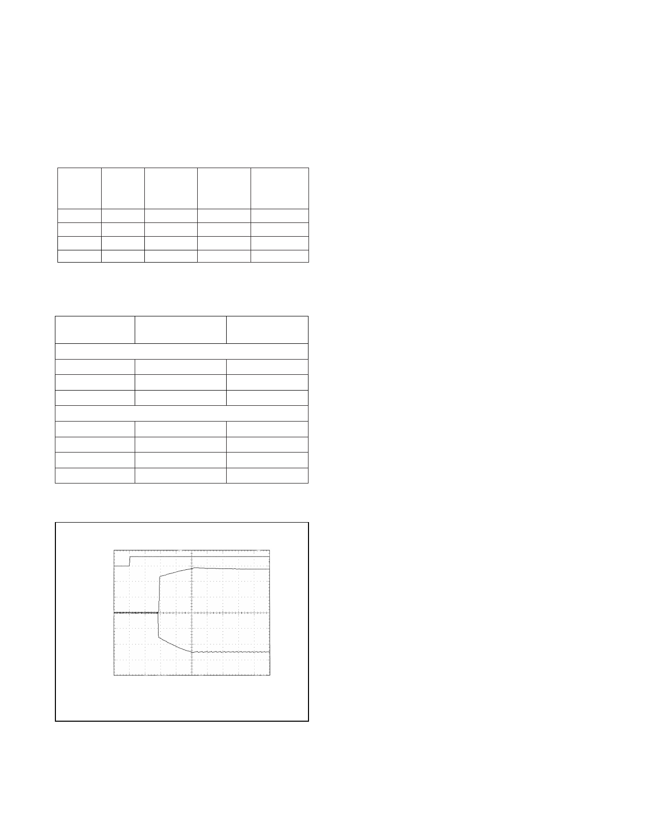
Transmitter Outputs when
Exiting Shutdown
Figure 3 shows two transmitter outputs when exiting
shutdown mode. As they become active, the two trans-
mitter outputs are shown going to opposite RS-232 lev-
els (one transmitter input is high, the other is low).
Each transmitter is loaded with 3kв„Ұ in parallel with
2500pF. The transmitter outputs display no ringing or
undesirable transients as they come out of shutdown.
Note that the transmitters are enabled only when the
magnitude of V- exceeds approximately 3V.
Mouse Driveability
The MAX3241 has been specifically designed to power
serial mice while operating from low-voltage power sup-
plies. It has been tested with leading mouse brands from
manufacturers such as Microsoft and Logitech. The
MAX3241 successfully drove all serial mice tested and
met their respective current and voltage requirements.
Figure 4a shows the transmitter output voltages under
increasing load current at 3.0V. Figure 4b shows a typical
mouse connection using the MAX3241.
5V/div
T2
2V/div
T1
VCC = 3.3V
C1вҖ“C4 = 0.1ВөF
50Вөs/div
Figure 3. Transmitter Outputs when Exiting Shutdown or
Powering Up
_______________________________________________________________________________________ 9
Share Link: